Aqua-Rite SWG Cell w/Four Wire Thermistor

Apr 15, 2017
8
Bradenton, Fl
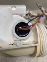
My three year old SWG is showing an error, “ Cold”, on the panel display. The SWG Cell has four wires coming out Temperature sensor side. I check the ohms for the blue and red wire and have 8700k ohms which sounds right for the temp. But what are the Orange and yellow wires going to and are they used.
I’ve read on other tech sites some RTD’s have a two wire thermistor and a two wire cold junction ref point for impedance correction. Does Aqua-rite use this? I’ve only seen ref. to a two, not a four wire temperature sensor. Any insight on this would be helpful, also I’m not sure which plug pins the Orange and yellow wires go to.
 
I need to clarify this is a rebuilt AquaRite T3 SWG that only had three years of service prior to failing, attached is a photo of label. I’m pretty sure previous owner ran the cell at 100% for 5k gal pool. One of the anode/cathode (black wire) connections on the plates had separated. The internal end plates showed the most wear, I.e. pitted with some small holes and surface corrosion, all the other plates looked perfect, no visible signs of wear, so I had the power connection rods welded onto good plates and place the outside plates in the center of the internal rack. The last photo of the side shows the four wires to the temperature sensor. The red and blue wire reads 8.7k ohms and responds to Temperature change. The yellow and orange wires show an open connection at the cell. The wires are good through the cable to the plug end. I’m thinking this is a four wire RTD system with the yellow and orange wires a junction point for impedance calculation by the panel software. I guess my question is could I just splice the wires together at the cell or is the junction reference point a specific resistance value? I guess I could measure this resistance on my newer cell in place to see how many ohms the panel expects to see. Hoping someone on the site has some experience with the temperature system.

Side note, I used a hack saw to open the cell at the original mfg. seam. A 4”pvc coupling with a little inner surface sanding makes a perfect fit over the Cell OD to be glued with pvc cement. If I repair another one I’ll make the cut dead center of the cell label area to get a good couple of inches of coupling width to glue. My 1/2” wide coupling band does hold pressure.(approx 25psi)
 

Attachments

  • 3125FC56-6CA8-45DA-B978-8D70D9B43CF8.jpeg
    3125FC56-6CA8-45DA-B978-8D70D9B43CF8.jpeg
    408.6 KB · Views: 6
  • 1BBA088F-185D-4E68-9EE3-365C56E9DACB.jpeg
    1BBA088F-185D-4E68-9EE3-365C56E9DACB.jpeg
    32.4 KB · Views: 8
  • B46CFBE1-470E-49D3-942C-2469F8FC7B62.jpeg
    B46CFBE1-470E-49D3-942C-2469F8FC7B62.jpeg
    16.2 KB · Views: 8
Another side note this SWG T3 cell temperature sensor looks to be a modular design that is glued in place. Does anyone have a source for the four wire temperature senso? I‘m sure with a little cautious excavation it could be remove from the cell and replaced.
 
OK, I am not sure about the 4 wires.

I suspect that if you connect a regular 10 k thermistor to the red and blue wires, it should work.

It basically has to work because someone might connect an old cell to the new board and the old cell only has two wires.

Just disconnect the yellow and orange wires.

1627323490978.png
 
Thread Status
Hello , This thread has been inactive for over 60 days. New postings here are unlikely to be seen or responded to by other members. For better visibility, consider Starting A New Thread.