Air flow problem

Wester97

Well-known member
Mar 31, 2019
65
Texas
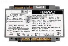
I’ve been replacing parts on my Jandy LAARS Lite and the latest attempt has one flashing lite which apparently indicates an air flow problem. But, I’ve yet to find a blower in my unit or in a parts diagram. Could this be talking about water flow and is just mislabeled? I have ~24v into and out of the flow switch that is readily available inside the access panel. Am I looking at the right thing?

thank you!!
 
The ignition control document says

1. Combustion airflow is continually monitored during the ignition sequence by the pressure switch (PSW terminal). If the pressure switch contacts remain closed for 30 seconds at the start of the ignition sequence without an output signal to the combustion blower, an airflow fault is signaled and the control will remain in this fault mode with the combustion blower off. If the pressure switch contacts later open while there is still a call for heat, the control begins the pre-purge period followed by a normal TFI sequence.

It is always closed because it has adequate water pressure, right?
 
While the pump is running, should the pressure switch be closed, regardless of if the heater is on? From the literature it seems like the ignition control module expects this to go from open to closed during the startup sequence.
 
You have no combustion/inducer blower It is a natural draft heater. It looks like your original Fenwal ignition module may be obsolete and has been replaced by another Fenwal ignition module that may need to be wired differentley than the original in order to work correctly. Did you get wiring instructiones with the new Fenwal Ignition control?
 
You have a water pressure switch which closes the contacts with water flow through the heater core. If the switch isn't holding there won't be any ignition or it may be short cycling due to the switch being defective. You can TEMPORARILY jump it out to see if it's the culprit.
 
I thought about jumping it, but I do see ~24v on both sides of the switch - that indicates that it is closed, right? The docs for the ignition controller talk about seeing the valve going from open to closed in the startup sequence. Does this sound right?

35-66 Models only:1. Combustion airflow is continually monitored during the ignitionsequence by the pressure switch (PSW terminal). If the pressureswitch contacts remain closed for 30 seconds at the start of the ignition sequence without an output signal to the combustion blower,an airflow fault is signaled and the control will remain in this faultmode with the combustion blower off. If the pressure switch contacts later open while there is still a call for heat, the controlbegins the pre-purge period followed by a normal TFI sequence.
 

Enjoying this content?

Support TFP with a donation.

Give Support
I am attaching 2 Fenwal photos. I think that the one that doesn't have " F1 & F2" contacts is the one that was originally installed on your heater. You'll notice that the fault codes on that one start at 2 flashes instead of 1 flash since your heater doen't have a blower motor/fan or "air flow switch". This older Fenwal may still be available from some sources?? I am sure that if you look at the wiring diagram on the inner left panel of the heater you will not see any connection points labeled for " F1 & F2". This leads me to believe that the newer Fenwal with the " F1 & F2" contacts is wired differently than the original In order to accommodate the slightly different igntion sequence in the newer Fenwal. Without knowing exactly how the newer Fenwal is wired in to the circuit It is difficult to troubleshoot and tell exactly what the problem is. But that said, I would guess that since the wiring on the newer Fenwal must have a wiring workaround in order to keep the ignition sequence from stopping at "air flow fault" (since it doesn't have an air flow switch), that the conclusion that I would come to is that it is wired incorrectly or you are losing a needed part of the circuit at some point.
 

Attachments

  • shopping.jpg
    shopping.jpg
    60.3 KB · Views: 4
  • 35-662904-113-2.jpg
    35-662904-113-2.jpg
    134.2 KB · Views: 3
This is how it looks, taken from the troubleshooting manual. Although I don't see the high-limit switches. I have 24v on both side of the pressure switch, so I think it's good to go. After step 5, I think what I might be missing is 24v on the yellow/black wire that leads to IND port. I assumed it was a problem with the board, but if that is coming IN to the board, then it would indicate a problem with the temperature control ... which was also replaced with a new R0058200.
 
Thread Status
Hello , This thread has been inactive for over 60 days. New postings here are unlikely to be seen or responded to by other members. For better visibility, consider Starting A New Thread.