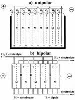
Regarding the cell configuration, electrolyzers may be constructed in either unipolar or bipolar design (Figure 8).
A unipolar (or “tank- -type”) electrolyzer (Figure 8a) consists of alternate positive and negative electrodes held apart by porous separators, i.e., membranes.
Positive electrodes are all coupled together in parallel, as are the negative electrodes, and the whole assembly is immersed in a single electrolyte bath (“tank”) to form a unit cell.
A plant-scale electrolyzer is then built up by connecting these units electrically in series.
The total voltage applied to the whole electrolysis cell is the same as that applied to the individual unit cells.
On the other hand, in a bipolar electrolyzer a metal sheet (or “bipole”) connects electrically adjacent cells in series.
As seen in Figure 8b, the electrocatalyst for the negative electrode is coated on one face of the bipole and that for the positive electrode of the adjacent cell is coated on the reverse face.
In this case, the total cell voltage is the sum of the individual unit cell voltages.
Therefore, a series-connected stack of such cells forms a module that operates at a higher voltage and lower current than the tank-type (unipolar) design.
To meet the requirements of a large electrolysis plant, these modules are connected in parallel so as to increase the current.
These two different cell configurations present different electrode reactions.
For the unipolar configuration, the same electrochemical reaction (either the HER or the OER) occurs on both sides of each electrode.
On the other hand, in the bipolar configuration, two different reactions (HER and OER) take place simultaneously on the opposite sides of each electrode not directly connected to the power source.
This means that one side of each electrode acts as a cathode and the other as an anode (although both sides are at the same potential), with the exception of the two end electrodes that are connected to the DC power source.
The resulting cell voltage for these two basic configurations is quite different.
For typical industrial processes, the unipolar configuration presents a cell voltage of about 2.2 V and the bipolar configuration has a value of 2.2 × (n − 1) V (where n is the number of electrodes).
Owing to the simplicity of the unipolar configuration, this type of electrolyzer is easy to fabricate and requires low maintenance, but presents high electrical currents at low voltages, causing large Ohmic losses.
On the other hand, the bipolar configuration has lower Ohmic losses in the electrical circuit connectors; however, it demands much higher precision in its design and manufacturing to prevent electrolyte and gas leakage between cells.
The gap between electrodes must also be considered during cell design.
It corresponds to the distance that the ions have to travel within the electrolyte.
A smaller gap has the advantage of less resistance to ionic transportation.
However, if the gap is too small, it can induce electric sparks, posing an explosion hazard.
An optimum electrode gap must be identified for each particular cell.
The electrolyte flow forces convective mass transfer in the cell.
At high current densities, electrochemical reactions are limited by the electrolyte mass transfer. Stirring and/or inducing turbulence reduces the concentration gradients in the electrolyte and enhances mass transfer.
An electrolyzer’s operating cell voltage is directly related to its energy consumption and electrical efficiency.
The cell is considered inefficient if a higher voltage is required to produce an equivalent hydrogen mass, while keeping the current constant.
The operating current density also defines the electrolyzer’s energy efficiency.
Conventional water electrolyzers generally run at current densities ranging from 1000 to 3000 A m −2 .
The current density determines the rate of hydrogen production, with higher current densities leading to higher rates of the electrochemical reactions.
However, fast bubble formation resulting from an increased rate of gas production also increases the overpotential due to the bubbles’ resistance.
Therefore, current density should be kept within a certain range, with compromises between the gas production rates and the energy efficiency.
The operating temperature is another important parameter.
Conventional alkaline water electrolyzers are designed to run at temperatures of around 80‐90 C.
Increasing the operating temperature has the advantage of decreasing the equilibrium cell voltage.
However, high temperatures increase water loss due to evaporation and require highly resistant materials to maintain the equipment’s structural integrity.
Last edited:


