About to Re-Plumb...Really need some expert advice

JSnake Repair

Well-known member
Apr 26, 2024
53
Texas
I have never really done much with PVC. Everyone I ask just tells me "it's easy", but some of the only helpful advice I've gotten is "use the least amount of elbows as possible". But I am very much designing a flow setup all by myself and I would really like to do it better than the people prior. The Swimming Pool Plumbing Repair Page is helpful...but leaves something to be desired.

So I think I have all the tools and equipment, just need to buy PVC...straight pipe, unions, and elbows (and maybe a valve).

I am doing most of the setup with 2" Schedule 40 PVC as before, the only part that might not be 2" will be at an end where I install a garden hose connector so I can drain the pool (as done prior).

My plumbing equipment to be connected:

  1. Pentair Challenger High Pressure Pump

  2. Polaris PB4-60 Booster Pump

  3. Hayward Swimclear CX020 (I believe X = 3)

  4. Hayward W3AQR15 Salt Generator

  5. Blue-White R320 Flow Meter

My Pipe Tools

  1. PVC Cutter (up to 2 1/2")

  2. PVC Deburring Tool (up to 3.5")

  3. PVC Pipe Saver (1.5" and 2")

My Pipe Expendables

  1. Weld-On P70 Primer

  2. Weld-On 724 CPVC

  3. Magic Lube

  4. Teflon Tape

Current Setup

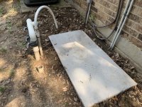
Fortunately all the underground pipes are good, and the above ground pipes can be connected to. As pictured, I have an empty 2x4 poured concrete slab (foam reinforced) next to the 3-to-1 intake, main 2" return, and smaller booster pump return (will not be reusing the hose or connector).

IMG_0404 2 Large.jpeg
IMG_0403 Large.jpeg

Previous Setup
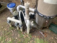
Previously there was a tab feeder (no chlorinator), no flow gauge, and no way to bypass the booster pump. Additionally, no unions were used on the Pentair pump...making repairs troublesome. (The whole thing leaked and was falling apart btw). Otherwise, the setup will be very similar to before (pictured; booster pump is manually bypassed here). Will be reusing the Jandy valves (via pipe saver), as well as buying a new three way for the booster pump.
IMG_9958.JPG

IMG_9957.JPG
So what are my questions??

  1. I don't know what I don't know. Is there anything else I should be adding to my setup?

  2. I am most concerned that my Pentair Pump volute will no longer line up perfectly with the 3-to-1 intake...what is the best route here if so?

  3. For the chlorinator, should I install it in a parallel pipe setup so as to allow for bypassing (as well as being able to properly balance the water before putting in operation)?

  4. Is there any magic to properly measuring the pipes and positioning equipment? What about installing unions?

  5. Any common mistakes or tips for success?


I might be overthinking this, but so much is riding on getting this pool running again and I both refuse to pay somebody to do it for me (really need to know how everything works and how it got there) as well as do it wrong/lazily myself. THANK YOU FOR READING.​

 
Get some 45s as well as 90s. Using two 45s can let you put a bit of a turn in the pipe to align the pump.

Layout the equipment and dry fit the pipe before you begin gluing.

You would like a bit of a straight pipe into the pump suction. Recommendation is usually 5X pipe diameter or 10” for 2” pipe. But even half that will do. Your pump is jammed between the wall and the inground pipe. I would try turning the pump 90 degrees but you don’t have any pad to the left of the pump. Consider extending the pad to give you more flexibility in the layout and not having the equipment jammed together.

Similarly you need a straight run from the filter though the SWG cell into the return pipe.

Spend some time with the equipment and try different positions and layouts to see what works best for fitting the plumbing. More space between equipment makes alignment easier.

PVC Repair - Further Reading Has more tips for you.
 
^^^What Allen said.

Make/draw a plan diagram…it doesn’t have to be fancy…just plan the rough placement for all the equipment and get an idea of all the fixtures you need.

Your pad is very tight. You might make it work but you should really consider an expansion…maybe by moving the filter to its own smaller, possibly less robust, homemade, pad to the right. That gives room for your two pumps and the straight piping runs needed for a few spots as Allen talked about. Dry fitting is very tough and it is not accurate for exact measurements but it is very useful for figuring out some connections. Be aware of the “stops” inside the PVC fixtures to measure how long to make each PVC length. You really want to insert the PVC to those stops for good connections.

If you have access to a chop saw, to me that is the easiest way to make cuts. When in doubt I make the piece a bit longer and then shave off a bit if needed (obviously before gluing). The piping is cheap if you need to discard/redo.

I wouldn’t put a bypass for the SWG, just buy a dummy cell and use that for the installation and any time you need to bypass in the future.

I would connect in this order:

1) Pump intake to suction manifold…align as necessary using 45s if needed. Build your “aligning pvc section” from the pump itself with a final horizontal glue connection to your manifold. I am assuming the pump has a union connection on its suction side. This gives you a bit of horizontal (not vertical) wiggle room using movement of the pump itself.

2) pump output to filter, you have some horizontal wiggle room for final connection to filter by moving the filter

3) filter output to returns…this is the last section and allows the final piece (SWG) to slide in place with its two unions. Build the return side from both sides (pool side and filter side) with the final puzzle piece being the SWG insertion. This is the spot where vertical AND horizontal alignment are important. I don’t know anything about booster pumps but does its suction side need to “take off” before or after the SWG? I would guess before but that will impact your flow meter. Where are you planning on putting your flow meter?

If you have have something misalign that you are not comfortable with…stop and redo. Better and much easier now than later.

Good luck.
1. Unfortunately, this IS the new pad. And the whole thing was such an ordeal I am going to have to make it work.
2. Dummy cell...so THAT's what it is for...thanks.
3. Will be putting the booster BEFORE the chlorinator...with a check valve in the middle.
4. Have no idea where I should be putting the flow gauge...but with that insight I guess I should be putting it after the booster and as close to the return as possible.
5. I am not quite as sandwiched as the photos depict, I think I can get a slightly longer run into the pump volute (assuming the 45's aren't too long); additionally, the Hayward manual shows the cell counting as the straight run...so I'm good on that end.

Other advice noted...thanks.
 

Attachments

  • Screenshot 2024-06-12 at 2.15.31 PM.png
    Screenshot 2024-06-12 at 2.15.31 PM.png
    244 KB · Views: 5
  • Like
Reactions: jonpcar
What about Teflon Tape? Should I be using that ANYWHERE there is threads? A brief read of this article suggests:
  1. Apply in clockwise fashion
  2. Use 3 layers
  3. Do not over tighten
  4. Use "Permatex #2 or other silicone thread sealant, before wrapping with Teflon tape."
  5. "Teflon Tape is not recommended by some manufacturers, due to the lubrication it provides,"
So, will tape be a problem with my setup? Is silicon thread sealant really also needed?
You mean in unions? Nope, no teflon nor anything else to seal threads. The only element that seals is o-ring. Cover o-rings with a thin layer of silicone grease. It is important to realize that components connected with unions have very little room to wigle - they need to be exactly "in line", both horizontally and vertically.
 

Enjoying this content?

Support TFP with a donation.

Give Support
Thread Status
Hello , This thread has been inactive for over 60 days. New postings here are unlikely to be seen or responded to by other members. For better visibility, consider Starting A New Thread.