Pump sizing help for new inground design

Drewskii said:
I see...Is the order of the outgoing pipes based on the distance to the termination point...the most distant point closest to the pump?

The order should not matter. Although I would advise using true pool valves (like Neverlube) instead of pvc ball valves which can leak and break.

Also you could use 3-way valves instead of or in combination with 2-way valves.

Like on suction a 3-way to select between floor drain and skimmers and a 2nd 3-way or a couple 2-way valves to adjust between skimmers.

Or more useful, on the return side a 3-way selecting between bubblers and the other returns and then 2 ways to adjust the normal returns. This allows you to only have to turn 1 valve to turn on and adjust the flow for the bubblers and not having to turn 4 valves (open the bubblers and partially close the other returns)

A side conversation on TDH and forum policies has been split off to here. JasonLion
 
Here is my attempt at the plumbing for the three bubblers.

Based on my understanding of the hydraulics, the 2 1/2" loop creates a constant pressure on all three 1 1/2" lines to the bubblers. However, if there is a more efficient way to do this please tell me.

The length of each bubbler pipe has been equalized taking into account the fittings as shown. However, when optimized for the 30 GPM required for the maximum plume on the bubbler (23" high above a 6" depth of water) the equalization of the TDH suffers somewhat at 20 GPM. I don't know if it is a significant difference or not. Would it be better to try to split the difference or is it not worth the effort?

I assume the TDH for fittings varies based on flow but can't seem to find a chart that quantifies that.

Edited: I mistakenly calculated the friction losses at 100 times the actual amount. Please simply move the decimal point. For instance, the loss per foot for 20GPM is NOT 2.6, it is ,026! I also noticed that the 12' length of the loop could probably be reduced to 4'. :oops:

Edit #2: These calcs are just wrong...operator error. Please see the revised attempt further below in the thread.
 

Attachments

  • Capture.JPG
    Capture.JPG
    41.6 KB · Views: 123
  • Capture.JPG
    Capture.JPG
    66.2 KB · Views: 123
Will you have access to the small bubbler lines? Might be easier eliminate the loop and just put a valve on each bubbler (or the first 2) to allow you to balance the flow.
 
First, the head loss for the fittings is not constant with flow rate.

Second, the loop is not really needed because the feed points for the bubblers are fairly close so it won't have much of a benefit. Loops only help when the feed points are fairly far apart.

Third, you don't really need equal flow because having the center bubbler a little higher than the other two might look better than having them all the same height.

Fourth, the difference in head loss is so small compared to the head loss in the exit orifice, you will probably not even notice the difference in height. It will be very subtle.

So did you not like the low flow bubblers?
 
Ah..the low flow bubbler...

The ColorCascade bubbler from Pentair is the one I'm planning on using. I'm actually quite surprised I can't find more than one other manufacturer of these things. This one also has LED lights I'm not even sure if I like.

My understanding is that the bubbler, in 6" of water, will vary in height based on the delivered GPM. The plume heights are indicated earlier in the thread. The height of the plume above the water is;

7" with a 3/4" fitting @ 15 GPM
12" with a 3/4" fitting @ 20 GPM
15" with a 3/4" fitting @ 25 GPM
23" with a 3/4" fitting @ 30 GPM

17" with a 1/2" fitting @ 15 GPM
No spec for 1/2" above 15 GPM that seems strange. I wonder what happens?

These things are expensive and the plume height at 12" or less will be at the top of the coping. That just seems like a bad buy if I can get the GPM there.
 
Sorry for the above attempt at the bubbler TDH flow. It may have been the wine :-D
Let me try again.

The charts I have do not indicate Total Losses In Equivalent Feet of Pipe for various flow rates. They simply carry one value. Perhaps Mark can indicate where such info could be found. Therefore, the values for Total Losses In Equivalent Feet of Pipe are constant at both the 20 GPM and 30 GPM flow rate.

That said, the difference in the TDH between the B bubbler and the A or C bubbler is 2.1' and 1 45 degree elbow.
 

Attachments

  • Capture.JPG
    Capture.JPG
    45.2 KB · Views: 109
  • Capture.JPG
    Capture.JPG
    81.8 KB · Views: 109
jblizzle said:
Will you have access to the small bubbler lines? Might be easier eliminate the loop and just put a valve on each bubbler (or the first 2) to allow you to balance the flow.

Nope, no access.

But I do like the idea of being able to control each bubbler. It's just mo money so we shall see how it goes.
 
Did you read my previous post?

mas985 said:
First, the head loss for the fittings is not constant with flow rate.

Second, the loop is not really needed because the feed points for the bubblers are fairly close so it won't have much of a benefit. Loops only help when the feed points are fairly far apart.

Third, you don't really need equal flow because having the center bubbler a little higher than the other two might look better than having them all the same height.

Fourth, the difference in head loss is so small compared to the head loss in the exit orifice, you will probably not even notice the difference in height. It will be very subtle.

You are still not calculating head loss correctly. But again, it just doesn't matter.
 
I thought the Total Losses In Equivalent Feet of Pipe Method accounted for the flow rate. If not, could you explain how to do it?

I understand that in this case the loop may not be needed but wanted to understand the method of calculating a loop anyway.

Edit: Here is a link for an explanation of calculating pressure loss using the Equivalent Feet of Pipe Method including a spreadsheet you can download.

http://www.engineeringtoolbox.com/equiv ... d_804.html
 
You can use equivalent length to calculate head loss although it is not quite as accurate as other methods but it isn't that bad. However, the equivalent lengths for fittings that EngineeringToolBox is not the same as the Crane TP-410 manual which is the bible of hydraulics so I use the latter.

But there are a couple problems with the way you pieced together the problem:

1 - You are mixing pipe sizes and the equivalent length for the fittings is not the same between pipe sizes.

2 - You are mixing parallel with series paths and parallel paths (e.g. loop) require special handling.

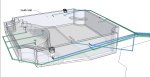
3 - The flow rate is not the same in the loop as in the individual pipes so you can't calculate those together. Plus the flow rate in the loop is not a constant in all parts of the loop. Flow is split on either side of the loop but not equally and as flow is dumped to each pipe, it changes in the loop. So the loop and the pipes must be calculated separately.

The loop is not an easy calculation and requires several equations for each node with several unknowns to get the flow rate in each segment of the loop. Here is an example of a network node analysis: http://en.wikipedia.org/wiki/Pipe_network_analysis

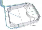
So I would simply ignore the loop because in reality it doesn't play a significant role and will not alter the results by very much. Ideally, you want the three pipes to be fed by a large header (again loop not required) and the feed points to be close together. The objective is to have the pressure between the three pipes to be a close as possible. Then you can make the three pipe head loss close to being the same. This will make the flow rate close to being the same.

Also, you can't ignore the exit orifice since that is were most of the head loss will occur. Jet nozzles have a more complicated head loss calculation because there tends to be a lot of transitions. Here is a rough approximation based upon some empirical formulas:

Jet Head Loss (ft) = (0.0026*(1+( 0.6*((1-(JD/PD)^2)^2))))/(JD^4) * GPM ^ 2

JD = Jet Diameter
PD = Pipe Diameter

For a 0.75" jet and a 1.61" pipe, it reduces to

Jet Head Loss (ft) = 0.011264 * GPM ^ 2

Next for the fittings, each 90 or 45 can be represented as a constant independent of pipe size, equivalent length over pipe diameter (LOD). Per Crane TP-410:

90 Ell LOD = 30
45 Ell LOD = 45
TEE Branch LOD = 60

So for a 1.5" pipe

90 Ell Leq = 30 * 1.61 / 12 = 4.025'
45 Ell Leq = 15 * 1.61 / 12 = 2.0125'
TEE Branch Ell = 60 * 1.61 / 12 = 8.05'

And for a 2.5" pipe

90 Ell Leq = 30 * 2.469 / 12 = 6.1725'
45 Ell Leq = 15 * 2.469 / 12 = 3.08625'
TEE Branch Ell = 60 * 2.469 / 12 = 12.345'

Note that you must use the actual pipe I.D. in these formulas.

But again, the 2.5" pipe loop will not be easy to calculate and not really worth the effort.

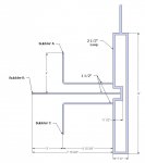
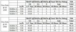
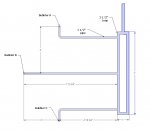
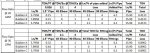
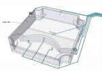
But for each of the bubbler pipes, I get the following plumbing curves:

Pipe B Head loss (ft) = 0.01212 * GPM ^2
Pipe A&D Head Loss (ft) = 0.01225 * GPM^2

Or basically a 1% difference in head loss but since head loss must be the same between the pipes, this actually means the flow rate will be about 0.6% different which is very small.

Here is a simple spreadsheet that does the calculation.

https://docs.google.com/spreadsheet/ccc ... nX0E#gid=0
 

Enjoying this content?

Support TFP with a donation.

Give Support
Thanks Mark,

Clearly the calculation is beyond my pay grade. On the other hand, the more info I have, the more comfortable I am with making decisions. Maybe the best path is to provide some drawings that show the overall design of the plumbing and the experts can just provide their opinion.

I can't overstate the benefit of TFP. It is an amazing forum and I encourage anyone who takes advantage of the FREE advice and help to JOIN by becoming a TroubleFreePool.com Supporter!
 
The design can be very simple. A single 2 1/2" pipe feeding the three bubbler pipes. Optionally, you can use a 4-way in the middle of the header pipe to feed the header and make it a bit more symmetrical. But the difference in flow rate is going to be so small that I doubt you will even notice it.
 
One port for each bubbler and one port for the pipe from the pump. Like a pitch fork. In the middle is the four way splitter.

Code:
---------------------|
                     |
                     |
---------------------+----------------- Pump
                     |
                     |
---------------------|
 
Here is a preliminary layout for comments

There are:

8.700 gallons in the pool
Three 2" returns
One 2.5" bubbler return

Two skimmers
One 34" channel drain
One 2" dedicated suction line

So there are four pipes on each side of the pump. Does that mean that the flow rate is equally divided by four on each side of the pump?

Assuming a flow rate of 30 GPM to each bubbler, what is the minimum flow rate required?

Bottom line, what size pump is required? VS I assume.
 

Attachments

  • Capture.JPG
    Capture.JPG
    133.4 KB · Views: 79
  • Capture.JPG
    Capture.JPG
    125.9 KB · Views: 77
  • Capture.JPG
    Capture.JPG
    100 KB · Views: 78
Drewskii said:
So there are four pipes on each side of the pump. Does that mean that the flow rate is equally divided by four on each side of the pump?
The flow rate through each run will depend on the head loss through each run so the longer runs will have less flow rate than the shorter runs. But since you have a valve on each, you can adjust the flow rate to whatever you want.


Assuming a flow rate of 30 GPM to each bubbler, what is the minimum flow rate required?
It depends on what you want to be able to run at the same time. 3 bubblers running at 30 GPM each would require a total of 90 GPM. If you want to run the normal returns with those, you will need more flow rate.


Bottom line, what size pump is required? VS I assume.
Again, it depends on what you want to be able to run at the same time. But a 2 FRHP minimum for just the bubblers. If you want full returns and bubblers at the same time, you would probably need two pumps.

Are you planning for automation?
 
Well ideally, I would like to run the entire system on one VS pump. I don't know enough about automation and actuators to be able to figure out what to do. For instance, is it possible to set it up so that when the bubblers are on, the other returns close and when the bubblers are off they open and the bubblers close?
 
Yes, that's why I asked. But it depends on the controller unit. Some allow grouping of functions so you can setup a bubbler function which puts the pump on high speed and shuts off the returns simultaneously. But most controllers handle spa mode which could also be used to turn on the bubblers and change pump speed even though you don't have spa. Basically it just switches valves and changes the motor speed at the same time. The Intelliflo does have a quite a bit of power so it might be able to run the bubblers and the returns at the same time although you might still need to shut down the returns a little bit to redirect most of the flow to the bubblers. The actuators can do this.
 
Could you suggest some configurations? I assume a control board, some multi port valves, and actuators are involved.

I also have some data I could post on length of each line and fittings as shown in the drawings if that would help.
 

Enjoying this content?

Support TFP with a donation.

Give Support
Thread Status
Hello , This thread has been inactive for over 60 days. New postings here are unlikely to be seen or responded to by other members. For better visibility, consider Starting A New Thread.