Purchased a home with a Aqualink RS and iAqualink 2.0 set-up. The iAqualink 2 has no lights on it when the Aqualink RS is powered on. I opened the Aqualink RS and it looks correctly plugged into the correct port. Is the iAqualink likely dead?

Aqualink RS, No Power to iAqualink 2
- Thread starter Rangers4me
- Start date
You are using an out of date browser. It may not display this or other websites correctly.
You should upgrade or use an alternative browser.
You should upgrade or use an alternative browser.
- Jul 21, 2013
- 65,062
- Pool Size
- 35000
- Surface
- Plaster
- Chlorine
- Salt Water Generator
- SWG Type
- Pentair Intellichlor IC-60
Welcome to TFP.
Check the voltage between the red and green wires at the red terminal bar (terminals 1 and 4). If the voltage is between 8 and 10 VDC, check the polarity. The red wire is positive (+) and the green wire is negative (-).
If you have voltage at the antenna then some LED should be lit.
Post pictures of the PCB and antenna board connections.
Jandy Troubleshooting Manual for AquaLink® RSAll Button and OneTouch™ Control Systems covers many common problems.
Thanks for your suggestions. It does look like from the multimeter readings that it is giving power from the Aqualink RS to the iAqualink 2.0 cable (22.5V). I removed the red cable on the far left and reseated it, but the lights to the iAqualink 2.0 still don't turn on.Welcome to TFP.
Check the voltage between the red and green wires at the red terminal bar (terminals 1 and 4). If the voltage is between 8 and 10 VDC, check the polarity. The red wire is positive (+) and the green wire is negative (-).
If you have voltage at the antenna then some LED should be lit.
Post pictures of the PCB and antenna board connections.
Jandy Troubleshooting Manual for AquaLink® RSAll Button and OneTouch™ Control Systems covers many common problems.
Attachments


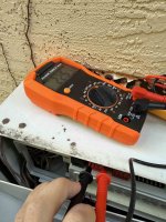

Are you getting 10 volts DC between the two spots with the red dots?
Can you pull the circuit board and show the back side?

The power center supplies the controller 10 VDC via the two (2) outside wires (red and green) of the four (4) conductor cables.
If the voltage drops below 8 VDC, the display will flicker on and off.
The two (2) inner wires (yellow and black) provide the two-way communication link between the controller and the power center.
They communicate via serial communication, using signals like the standard "RS-485".
Can you pull the circuit board and show the back side?
The power center supplies the controller 10 VDC via the two (2) outside wires (red and green) of the four (4) conductor cables.
If the voltage drops below 8 VDC, the display will flicker on and off.
The two (2) inner wires (yellow and black) provide the two-way communication link between the controller and the power center.
They communicate via serial communication, using signals like the standard "RS-485".
Last edited:


The most I’m getting between red and green .1-.3. The middle two wires (yellow and black) I get 3.4. I’m getting nothing at the lights.
I’ve attached a photo of the back of the board.
I’ve attached a photo of the back of the board.
Attachments


Last edited:
MikeB21036
Gold Supporter
Sorry, I'm a novice to this. Setting the multimeter to DC, these were the readings. Let me know if that's what you were looking for.
Aqualink RS
Red-Green 10.3
Blue-Yellow 1.8
iAqualink 2.0
Red-Green 0.4
Blue-Yellow 1.8
Aqualink RS
Red-Green 10.3
Blue-Yellow 1.8
iAqualink 2.0
Red-Green 0.4
Blue-Yellow 1.8
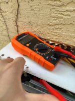
If you have good voltage at one end and not the other end, it is probably a bad wire.
Open up this tangled red wire to see if it is ok.
You can replace the wire to see if that helps.
The round thing might be a Ferrite bead.
Ferrite beads are found on cables used on electronics equipment such as computers, TV's, communication devices.
The Ferrite “bead” is actually a hollow round cylinder that fits around a wire(s) and often is covered in plastic to keep it in place.
Last edited:
Thank youIf you have good voltage at one end and not the other end, it is probably a bad wire.
Open up this tangled red wire to see if it is ok.
You can replace the wire to see if that helps.
View attachment 624423
TFP is a registered 501(c)3 non-profit that is maintained by user donations.
All of our content is free of advertisements.
Please consider donating at:

 www.troublefreepool.com
All of our content is free of advertisements.
Please consider donating at:
Become a TFP Supporter
Help Support TFP Trouble Free Pool is run by a dedicated group of volunteers that … Read more…
www.troublefreepool.com
Not yet. Haven’t been able to try yet.Did you get it fixed?

@JamesW Thanks for your help, I ended up finding a small tear in the cable running along the wall and was able to splice it. I also changed out the antenna, which seemed broken as well. We're now back in business.
Interestingly enough, even though the LAN/Internet lights now work, connects to the internet, and the iAqualink is running fine, the red power LED appears to be dead.
Interestingly enough, even though the LAN/Internet lights now work, connects to the internet, and the iAqualink is running fine, the red power LED appears to be dead.

