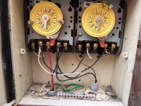
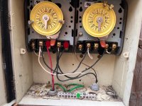
Got the cell installed and salt in so am down to wiring the controller and have nearly zero understanding of wiring. Here's a photo of the Intermatic switch. The pump is wired to the left switch and the switch on the right isn't used. The wiring photo in the RJ 60 manual shows it wired into the Load1and Load2 (each measures 120 volts) and Ground of the switch, same terminals the pump uses. That would be the third and fifth screws from the right. Does that mean it's operating at 240 volts and I leave that default setting in the controller alone? And does the ground wire connect to the bare ground that's coming in from power on the right side? Thanks.


