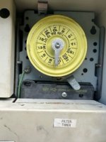
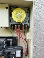
I'll take pics nowShow photos of the wire connections at the bottom of the timer. For 240 volt, the Line side terminals are 1 and 3. Load side are 2 and 4.

SWG Generator Question
- Thread starter Ron55
- Start date
You are using an out of date browser. It may not display this or other websites correctly.
You should upgrade or use an alternative browser.
You should upgrade or use an alternative browser.
- Apr 10, 2018
- 5,530
- Pool Size
- 18375
- Surface
- Plaster
- Chlorine
- Salt Water Generator
- SWG Type
- CircuPool RJ-45
Sorry Ron, but you're going to have to take the front cover off the load center and remove the black cover that's just under the timer switch.

I have the CYA up to 55. My FC was 8 yesterday and today it is 11 so I turned the % down to 5%.
We have company over. The pool is clear but is it safe to swim at that chlorine level?
We have company over. The pool is clear but is it safe to swim at that chlorine level?
- May 3, 2014
- 59,366
- Pool Size
- 6000
- Surface
- Fiberglass
- Chlorine
- Salt Water Generator
- SWG Type
- Pentair Intellichlor IC-40
At CYA of 55 (60), it is safe to SLAM level FC, which is 24 ppm.
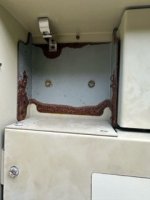
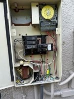
So I removed the cover on the sub panel.
Pics attached. My brother in law is helping. He thinks because the clips on the upper right side were broken and you cannot secure a 240 breaker they wired both the pump and the SWG to the one side.
Edited:
He said he can just move the wires for the pump to terminal 1 and 3 and leave the SWG on 2 and 4.
So the pump will always have power and can be controlled from its own internal timer and the SWG will be controlled by the rotary timer in the panel.
Does this make sense?
Attachments
Last edited:
- Apr 10, 2018
- 5,530
- Pool Size
- 18375
- Surface
- Plaster
- Chlorine
- Salt Water Generator
- SWG Type
- CircuPool RJ-45
Yes. Terminals 1 and 3 are always hot and Terminals 2 and 4 are switched.So I removed the cover on the sub panel.
Pics attached. My brother in law is helping. He thinks because the clips on the upper right side were broken and you cannot secure a 240 breaker they wired both the pump and the SWG to the one side.
Edited:
He said he can just move the wires for the pump to terminal 1 and 3 and leave the SWG on 2 and 4.
So the pump will always have power and can be controlled from its own internal timer and the SWG will be controlled by the rotary timer in the panel.
Does this make sense?
Success! Thanks to all for the help. Explosion averted.
Now on to the cell.
Now on to the cell.
So I finally got the opportunity to bring the cell in to be tested.
The cell passed the test and was making chlorine.
Should I replace the circuit board next?
The cell passed the test and was making chlorine.
Should I replace the circuit board next?
C0d3Sp4c3
Well-known member
- Dec 10, 2018
- 266
- Pool Size
- 20000
- Surface
- Plaster
- Chlorine
- Salt Water Generator
- SWG Type
- Hayward Aqua Rite (T-15)
What you have is the newest sw r1.59, the most reliable aquarite mainboard that you can find. Focus on the cell or get a replacement cell and test away.So I finally got the opportunity to bring the cell in to be tested.
The cell passed the test and was making chlorine.
Should I replace the circuit board nex
If the % dial and the display do not match or fluctuate, you have the following options.
1. Remove the disp bd and spray the potentiometer with an electronic cleaner.
2. Replace the 4-pin, 10kΩ, D-shaft potentiometer or ask someone to solder for you.
Digi-Key Part Number: 118-PTV111-4420A-B103-ND
3. Replace the display bd: GLX-PCB-DSP
How to use a contact cleaner...
I realize the cell is near the end of its expected life but if the cell is generating sufficient chlorine why do I need to replace the cell right now? Does the cell read the level of salt in the pool or is that done from the electronics within the Aquarite?What you have is the newest sw r1.59, the most reliable aquarite mainboard that you can find. Focus on the cell or get a replacement cell and test away.
If the % dial and the display do not match or fluctuate, you have the following options.
1. Remove the disp bd and spray the potentiometer with an electronic cleaner.
2. Replace the 4-pin, 10kΩ, D-shaft potentiometer or ask someone to solder for you.
Digi-Key Part Number: 118-PTV111-4420A-B103-ND
3. Replace the display bd: GLX-PCB-DSP
How to use a contact cleaner...
C0d3Sp4c3
Well-known member
- Dec 10, 2018
- 266
- Pool Size
- 20000
- Surface
- Plaster
- Chlorine
- Salt Water Generator
- SWG Type
- Hayward Aqua Rite (T-15)
No need to replace the circuit bd either unless it's dead. You have the newest sw r1.59, it's a keeper. If you're having issues producing chlorine, focus your troubleshooting on the cell.I realize the cell is near the end of its expected life but if the cell is generating sufficient chlorine why do I need to replace the cell right now? Does the cell read the level of salt in the pool or is that done from the electronics within the Aquarite?
Comparing the instant salinity readings between the preset start and stop run time will help you determine the performance of the cell.
Hayward Aquarite SWG - Further Reading
Determining Salinity
Thread Status
Hello , This thread has been inactive for over 60 days. New postings here are unlikely to be seen or responded to by other members. For better visibility, consider Starting A New Thread.