Jandy 1400 Power Transformer Burned...And?

Wow, that is indeed a large and unusual system for a residential pool. For the swg you have two choices that allow you to keep most of your RS system. First, replace the defective parts in the 1st box. Sounds like it's a transformer and board. Or you can scrap the Jandy swg and convert to a 3rd party like Circupool and use the RS to control the swg on-off and run-time plus everything else in your system. I'd go with the latter for reasons explained above unless the repair to Jandy swg is much cheaper than it appears.

Can you please add your signature? It will help all the experts understand what you really have and what your options are without guessing. It's very easy, here's how.

I hope this helps.

Chris
 
You have a very large system it would be a LOT of money to replace it all. Has the system ever been upgraded from a PDA system? This would be an upgrade called "IQ20-RS". Once upgrade, it would be an "RS" system now with web, Alexa and phone app capability.

What version/rev Aqualink do you have? This should be on the PDA startup or information screen somewhere.
Thanks, I think if I had to replace it all it would be well beyond my intention. The Aqua Palm version is 4.0 and includes in indoor wired component as well.
 
Wow, that is indeed a large and unusual system for a residential pool. For the swg you have two choices that allow you to keep most of your RS system. First, replace the defective parts in the 1st box. Sounds like it's a transformer and board. Or you can scrap the Jandy swg and convert to a 3rd party like Circupool and use the RS to control the swg on-off and run-time plus everything else in your system. I'd go with the latter for reasons explained above unless the repair to Jandy swg is much cheaper than it appears.

Can you please add your signature? It will help all the experts understand what you really have and what your options are without guessing. It's very easy, here's how.

I hope this helps.

Chris
Thanks Chris, will do. It has been a handful. I can safely say I've jumped into the "deep end" of pool ownership... :)
 
How big is your pool? I have about a 37k gallon pool and the installers had to put 2 Jandy cells in for my pool (twice the expense to repair/replace). My one Circupool RJ60 is holding chlorine at 8-9ppm running 25-30%. It was a game changer for me.
Thanks...my pool is listed as 22500 gallons. The deep end is about 12 feet or so. I've attached a picture for reference.

Bill
 

Attachments

  • Pool.jpg
    Pool.jpg
    82.2 KB · Views: 20
I was thinking that they had an APURE1400 based on the title, but it might be something else.

If it is the components in an automation box, then they probably just need the circuit board.

I suspect that the transformer plug can be replaced.

The transformer might be ok.

The cost of the transformer and circuit board are usually high enough that it's a better choice to get a new model box and mount it separately.

If the cell is 11 years old, it is probably close to its end of life.
Based on pricing it out, the transformer is about $350, and the board, depending on repair versus replacement is about $95 to $150. As for the cell, I have another one already on standby that's about a year old or so. Given that, the cost I'm in for so far is about $500 or so, again, give or take. Replacing the whole system has got to cost a lot more than that I'm thinking. If I were starting new, I can assure you I would not go with Jandy, it's been a pain in the... well...you know. But to rip the whole system out and start over seems extreme at this point.

You think that with the transformer plug being burned like that it's not that the transformer itself is bad? Is there a way to check that out?

Thanks again...Bill
 
I think that I would replace the circuit board and the transformer plug and see if it works.

My initial recommendation to replace everything was based on my incorrect assumption of what you had from the available information.

It’s important to try to provide as much detailed information as possible to allow assistance to have a complete picture.
 
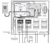
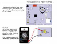
The transformer has 4 wires going in to the primary side.

This is usually 2 sets of 120 volt windings that are connected in parallel to a 120 volt source or in series to a 240 volt source.

Each set of windings will usually test at about 2 to 3 ohms.

The secondary of the transformer can have a single pair of wires or multiple wires depending on the number of voltages that the secondary output needs to have.

The transformer is a multi-tap transformer.

The multi-tap transformer allows the system to adjust the voltage going to the cell to control performance.

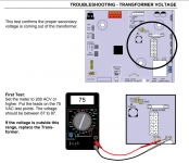
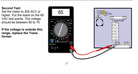
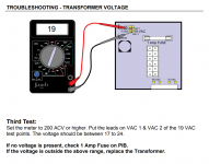
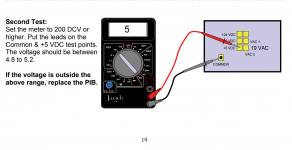
I don’t know the exact wiring for the transformer, but if you can figure it out, test the resistance of the primary windings and then test the voltage of each output voltage.

1623638094706.png
 
1623639840742.png
1623639924562.png
1623639997172.png
1623640082762.png

1623640130805.png
You can check the voltage and current going to the cell where the cell cord connects to the wiring inside the box.

full
 
  • Like
Reactions: PoolGate
I think that I would replace the circuit board and the transformer plug and see if it works.

My initial recommendation to replace everything was based on my incorrect assumption of what you had from the available information.

It’s important to try to provide as much detailed information as possible to allow assistance to have a complete picture.
Excellent. Thank you!
 

Enjoying this content?

Support TFP with a donation.

Give Support
This looks like a connector failure. It's very common in high current applications like this. Transformer failure is unlikely. When they do fail they let you know with lots of heat damage and a really nasty smell as they usually fail with a winding short. You've got heat damage, but at the connector.

If this was mine, I'd cut off the two failed contacts in the transformer socket, plug the connector back in and solder the two free wires to the back of the board. If that works, leaving it that way is an option until something else fails. Replacing the transformer connector is easy, if you can identify it. Removing the PCB connector can be challenging without the necessary tools & skill.
 
Last edited:
  • Like
Reactions: C0d3Sp4c3
This looks like a connector failure. It's very common in high current applications like this. Transformer failure is unlikely. When they do fail they let you know with lots of heat damage and a really nasty smell as they usually fail with a winding short. You've got heat damage, but at the connector.

If this was mine, I'd cut off the two failed contacts in the transformer socket, plug the connector back in and solder the two free wires to the back of the board. If that works, leaving it that way is an option until something else fails. Replacing the transformer connector is easy, if you can identify it. Removing the PCB connector can be challenging without the necessary tools & skill.
I was just wondering how I would make the connection work. I looked and can’t find that end piece. Great idea, I’ll try it.
 
I was just wondering how I would make the connection work. I looked and can’t find that end piece. Great idea, I’ll try it.
I have to agree with member CA92807 (post# 32) on this. The connectors are available but replacing them would require some desoldering/soldering skills, Molex A/B crimp tool, Molex Insertion tools and a lot of patience! If it were me, I'll cut the two yellow wires closer to the connector. Solder pigtails directly in the back of the board opposite the two burnt pins. Make sure the pigtail wire gauge is at least the same as the yellow wires and are long enough to run underneath the pcb and to the yellow wires. Use an insulated spade connectors to establish secured connections between the yellow wires and the pigtails. The two yellow wires are interchangeable. The M/F insulated spade connectors are available at your local hardware or auto supply. And don't forget to grab a crimper tool if you don't have one. Test away!
Connector.jpg
 
Last edited:
I have to agree with member CA92807 (post# 32) on this. The connectors are available but replacing them would require some desoldering/soldering skills, Molex A/B crimp tool, Molex Insertion tools and a lot of patience! If it were me, I'll cut the two yellow wires closer to the connector. Solder pigtails directly in the back of the board opposite the two burnt pins. Make sure the pigtail wire gauge is at least the same as the yellow wires and are long enough to run underneath the pcb and to the yellow wires. Use an insulated spade connectors to establish secured connections between the yellow wires and the pigtails. The two yellow wires are interchangeable. The M/F insulated spade connectors are available at your local hardware or auto supply. And don't forget to grab a crimper tool if you don't have one. Test away!
View attachment 345559
I like it. I like it a lot. Much easier than trying to solder and less risk of damage just in case I still need a transformer. Riddle me...Any clue on how to get the end point small enough to fit into the connector?

Thanks...
 
Last edited:
So...problem solved. After trying to figure out if I needed a new transformer, then how I would either replace the end plug on the transformer (can't find them), or solder the wires directly to the pins on the card (doable but difficult) and doctoring on several of the insulated spade connectors to see if one would fit (I think I got one to work, but it was questionable) it was all for naught. When I looked at the molex connector on the transformer again, the male pins were still in tact. I placed the card in the system, connected the transformer and, voila...I'm producing chlorine with no error messages.

Thanks to all for you patient guidance. You saved me the price of a new transformer, which I sincerely appreciate.

Bill
 
Thread Status
Hello , This thread has been inactive for over 60 days. New postings here are unlikely to be seen or responded to by other members. For better visibility, consider Starting A New Thread.