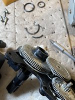
CVA24-T Actuator Details

I forgot to account for inertial reference frames in non-Newtonian space-time.

Good catch. :goodjob:

Here is the debug error information.

"debug_error": {
"errorCode": "api.invalidparam",
"errorMessage": "An error occurred. Please try again later.",
"wA": "GENERIC_WITHOUT_LINK",
"Ak": "",
"vJ": "invalidVideodata.1;a6s.1"

Does this link work -


  • Like
Reactions: JamesW
Yes, that works.

I think YouTube embedded videos are still a bit wonky with the forum update and older browsers .... have you updated your Mosaic browser to the latest release? Also, your VT-100 terminal may need an updated driver board fir the CRT display in order to get HD video to work. I can send you a DIY update video on cassette - VHS or Beta MAX ?
 
  • Haha
Reactions: mknauss
  • Haha
Reactions: strategy400
So getting back to the subject matter at hand, that particular CVA definitely needs to have its limit switches replaced. I left the unit powered but the control switch off. When I came back to fiddle with it some more later on in the day, the motor would only work in one direction. I wiggled and activated the limit switches a few times and that got the motor running properly again. Bad limit switches are a typical problem with these actuators.
 
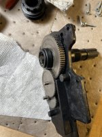
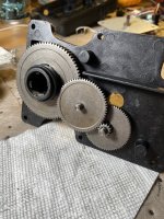
Gear box is in pretty good shape -

704DA390-1315-4C2E-A754-CB3FC47E3F67.jpeg
A6D81F49-C426-4FBB-BAD3-E0E86A9B6F2D.jpeg
BA9740F3-ACD1-4EA0-AFD7-832007B64E2F.jpeg

Definitely had what looked like moly sulfide grease on them. I need to find an old tin can and some mineral spirits to clean off the metal gears with then wipe it all down and repack it with new grease. There’s two o-rings I’d like to replace but they look like standard sizes I can get down at the hardware store.

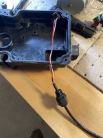
I think all-in if I just replace the limit switches and clean up the gear box, I should be able to get this one spare-worthy. I have a new wire harness for it and just need to find the right size lock nut to fasten it onto the body. They changed the style from a molded rubber boot to and plastic connector with a lock nut.
 
  • Like
Reactions: JamesW

Enjoying this content?

Support TFP with a donation.

Give Support
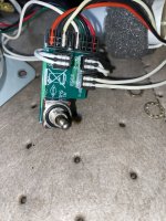
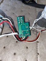
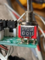
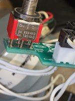
The toggle switch is solder mounted to a small circuit board where all the other connectors attach to. I’ll take a close picture when I get home.
 
  • Like
Reactions: JamesW
Connectors Left & clockwise - limit switch 1, input power, motor, motor capacitor, limit switch 2.

image.jpg

Backside starting at top and clockwise - DPDT switch, limit switch 2, motor cap, motor, input power, limit switch 1..
image.jpg
 
Last edited:
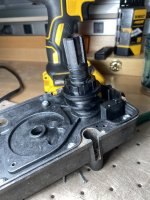
So everything except for the new power cord is complete. I had some issues with the old lower shaft o-ring seal as the old o-ring was brittle and broke -

FA8E6E70-227B-44AB-8070-FC0FB5E8935B.jpeg

I found a slightly smaller OD one at the hardware store but it worked fine. That o-ring isn’t super critical as it mostly acts as a dust/moisture seal. It’s so dry here and the bottom of the actuator faces the ground so moisture incursion isn’t an issue. The gears are packed with white lithium grease that I nabbed from the automotive section. I replaced both limit switches but the plastic post on the case on one side snapped off when I pressed the switch into place. It’s not a huge problem as the screw holds the switch in place but it could cause the switch to rotate a little and lose contact. I may put a dab of loctite (the removable kind) on the side to add a little extra hold.

Here’s another incredibly well made video by yours-truly showing it operating with the cams adjusted for 180-deg rotation -


The final assembly needs to be finished but I’m waiting on a new cable seal. At this point it’s a perfectly functional spare. In case any one is interested, when the motor is running it draws ~0.5 amps at 24VAC. I did measure a constant leakage current of 20mA or so it’s interesting that these actuators constantly draw about 1/2 Watt of power. I’m sure the EasyTouch panel draws plenty of standby current too so a 1/2W isn’t all that concerning.
 
The actuators are listed at 0.75 amps, which is probably under full load turning a valve.

It would be interesting to see what the actual full load amps are.

If you have a spare valve, maybe put the actuator on it and check the power draw.

I don’t have a spare valve so I guess I’ll just grab the actuator with my teeth and try to replicate the additional mechanical resistance that way .... luckily I have a dentist appt next week in case I need “restoration services” ...
 
  • Haha
Reactions: JamesW
Your dedication to pool science is unquestionable, but we can't ask you to put yourself at risk.

We will be able to check the power draw at some point.

Also, how could we verify the the applied bite force is an accurate representation of the resistance of a Jandy valve?

Perhaps if you practice opening and closing your actual valves by biting on the valve stem, you could calibrate the bite force resistance to a reasonable approximation.
 
Last edited:

Enjoying this content?

Support TFP with a donation.

Give Support
Thread Status
Hello , This thread has been inactive for over 60 days. New postings here are unlikely to be seen or responded to by other members. For better visibility, consider Starting A New Thread.