Intellicomm II Wiring

Rancho Cost-a-Lotta

Gold Supporter
Silver Supporter
TFP Guide
Apr 10, 2018
5,173
Rancho Cucamonga, CA
Pool Size
18375
Surface
Plaster
Chlorine
Salt Water Generator
SWG Type
CircuPool RJ-45
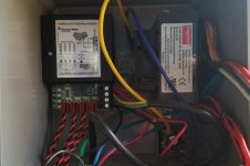
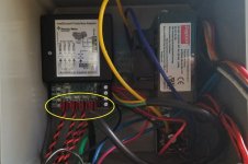
My Intelliflo VS is controlled by four switches routed to an Intellicom II Interface adapter which receives 24 volts from a transformer. The RS-485 data cable is connected between the Intellicomm and the pump data port. Any one of the four switches connected to the "Prog 1-4" connections activate the pump at the programmed speed.

Do the inputs "Prog 1-4" shown in the photo merely require any 9-24 volt AC/DC source to operate the programmed speeds?
Intellicomm 2.jpg
 
Mike,

Yes.. Basically the IntelliComm normally connects to the coil wires that would go to an automation relay.. So, instead of energizing a relay, it just tells the IntelliComm to run a speed..

What automation system do you have???

Thanks,

Jim R.
 
I didn't really want to publicly humiliate myself, but I'm gonna use a WiFi irrigation controller (24 VAC) to operate valve actuators and a couple of pump speeds. I'm just working out a few of the challenges. I've got the valve configuration/control figured out.
 
Mike,

Yes.. You go into the pump and program the pump so that when it is told to run Ext program #1 it will run at XXXX speed.. If told to run Ext program #2, it will run at ZZZZ speed, etc.

Keep in mind that the IntelliComm, needs 9 to 24 VDC to power the unit itself. While the Inputs to change speeds can be AC or DC..

Thanks,

Jim R.
 
  • Like
Reactions: Rancho Cost-a-Lotta
I got the wifi switch/relay module hooked up and it's working great for automated pump control.

I set up the irrigation controller for valve actuator control. It works, but since it can only operate one valve at a time, mode changes between pool-spa-waterfall are real slow and programming schedules is a pain. I'm now working on operating all valves using the same relays I used for the pump.

For the valves, I need 24 VAC power. From what I can tell, my 24 VAC transformer is connected to a "rectifier" to provide 24 VDC power. Can I just pull AC power off the blue/yellow leads going to the rectifier under the transformer?
20180317_081848.jpg
 

Enjoying this content?

Support TFP with a donation.

Give Support
I got the AC/DC figured out and got the switch wired to 24VAC. This should be the last question...famous last words.

I tested a valve and it works as expected. I have two options for wiring each valve.

Option 1: Use two relays per valve and wire each side to separate COM/NO terminals. Valve will turn in one direction when each relay is closed.

Option 2: Use a single relay and wire one side to NC and other side to NO. Valve turns one direction when relay is closed and other direction when relay is open.

One advantage with Option 2 is it will not allow voltage to be sent to both sides of the motor at the same time, so need to use the interlock feature on the relay.

When I tested voltage across the terminals with Option 2, I saw nearly around 40 volts across the NC/COM and NO/COM terminals. Is this normal?

What is the best option?
 
Mike,

Option 2 is how the actuators were designed to be driven.. There are a couple of capacitators in the circuit.. I forget what that type of motor circuit is called, but I would not worry about the apparent 40 volts spike..

Thanks,

Jim R.
That's all great news.

I appreciate all the help Jim!
 
Thread Status
Hello , This thread has been inactive for over 60 days. New postings here are unlikely to be seen or responded to by other members. For better visibility, consider Starting A New Thread.