Electrical question

rajung

Well-known member
Mar 17, 2015
468
Cedar Falls, Iowa
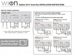
I am finally getting around to see if I like the Wion Outdoor Wi_Fi timer, the current Intermatic timer I wired in a couple years ago works perfect but would like to randomly run the pump if I add chems other than at my routine times .
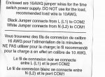
The timer has these ratings, not listing all but only what I would need.
N.O contacts
40A Resistive, 120 -277VAC
1HP, 16Amp FLA 96A LRA 120VAc
2HP, 10A, FLA 60A LRA 277VAC
My pump is a 1 1/2HP on 120 Voltage, would it be too under rated or ok?
Thanks
 
Why can't you manually turn on the Intermatic whenever you want to run outside of the schedule? That should not be an issue.

What is the amp rating on the motor label? Use that to determine if the timer is sufficient or not.
 
Pump manual states to connect to 20Amp service which it is, pump tag shows 12.4Amps.
I mounted the timer inside of a plastic weather proof box since it is metal and wanted to keep it from any rust since its mounted about 2 ft from the ground and out of snow, It has 8 screws for the cover and a bit of a hassle to get to the timer if I just want to adjust on/ off times.
 
So going back to the wion / woods WIFI timer, looking at the wiring instructions , I am confused on what it is showing, the timer came with a black and white set of jumper wires for the clock portion and it shows where to connect for a single load 120v as stated on piece of paper packaged with the 2 wires, but under the diagram for that install it shows the (J2) white wire connected to Neutral but not the COM 1.
 

Attachments

  • timer 1_LI.jpg
    timer 1_LI.jpg
    115.9 KB · Views: 9
  • timer 2 (2).jpeg
    timer 2 (2).jpeg
    263.6 KB · Views: 6
@rajung , I'll try to answer your question but first, a disclaimer:

The information below is provided for reference only. I make no statement, representation, or warranty about the quality, accuracy, context, completeness, availability or suitability for any purpose of, and you should not rely on, any information provided by me through this website. I disclaim all responsibility and all liability (including without limitation, liability in negligence) for all expenses, losses, damages and costs you or any other person might incur for any reason including as a result of the information I provide being in any way inaccurate, out of context, incomplete, unavailable, not up to date or unsuitable for any purpose. If you use this information or implement any of my suggestions, you do so at your own risk.

I don't recommend you wire this timer in on your own if you are not clear on how to do it. I suggest you ask a professional for help. At least, ask someone local that is comfortable with electrical work to assist you.

The diagram you circled is correct... but I understand how the J2 connection, the way it is drawn, can be confusing to the layperson.. J1 provides the 120VAC Line connection to the timer. Jumper J2 is not needed for your "One 120VAC load" configuration. J2 is only really required for the "One 240VAC load" configuration.

The way to do this for the single 120VAC load configuration you are asking about is as follows:
  1. Connect a jumper between the L and COM2 terminals, as illustrated.
  2. Your 120VAC Line feed can go to either one of the L or COM2 terminals. That means one of these 2 terminals will have 2 wires in it. Make sure they are the SAME AWG and pick the terminal that makes your wiring the neatest.
  3. As far as J2 goes, you don't need it in this configuration. Just connect both your 120VAC neutral feed AND your pump's neutral wire to the N terminal on the timer.
  4. The 120VAC Live connection for the pump goes to the NO2 terminal ( switched by the timer to the COM2 terminal at the set time(s), powering the pump ).
That's it.

WARNINGS
  • Make sure you use the same AWG (solid) wire throughout. Especially when putting two wires on the same terminal.
  • DO NOT use the supplied J1 or J2 since they are likely not the same wire gauge as your 120VAC feed and pump wiring.
  • Make your own jumpers from the same AC wiring used for your pump and/or 120VAC feed.
  • Never use stranded wire for screw terminals. They require solid conductors.
  • Never mix wire gauges when terminating 2 wires on the same screw terminal.


Sgt Wilko
 
Last edited:
  • Like
Reactions: MyAZPool
Thanks so much for that info, I did notice on the 240VAC diagram how the jumper was used which conflicted to me about the 120 set up, searching for diagrams on the net for this timer I found a 3rd version wire set up for a single 120 application direct from Woods which really stopped me from continuing until I found some more definite answers.
 

Enjoying this content?

Support TFP with a donation.

Give Support
Do you have the neutral line running through your T101 timer you are replacing?

The T101 only needs to switch the hot wire and the neutral may not be run through the timer box.
 
Last edited:
@rajung , Just realized the supplied jumpers with your WiOn are 16AWG. DO NOT USE THEM. You should not mix wire gauges under a same terminal.
Use ONLY solid wire of the appropriate gauge for your pump. Use separate lengths of that same pump wiring to create your jumpers. See example excerpted from the linked page in my previous post:
1563158269422.png
I'll edit my original post to avoid someone not seeing this warning post and making the mistake.
 
@rajung , Just realized the supplied jumpers with your WiOn are 16AWG. DO NOT USE THEM. You should not mix wire gauges under a same terminal.
Use ONLY solid wire of the appropriate gauge for your pump. Use separate lengths of that same pump wiring to create your jumpers. See example excerpted from the linked page in my previous post:
View attachment 111086
I did read about that this afternoon, makes sense since the gauge thickness would tilt the mounting plate.
 
Thanks for the breakdown SgtWilko, I have it working fine and a good wifi signal , now just to see how this style of timer holds up to the mechanical version. as far as that small section of paper about the jumpers that was bundled with the wires, seemed like it was a late update ( addendum) to a miss printed diagram and needed also for a single load to keep clock time after it switches off.
 
Last edited:
Glad I could help you get it working.
I'm not sure I understand what you mean about the jumpers and addendum, but the wiring scheme I suggested results in the timer always being powered (as it should), regardless of the pump being switched on or off. You do not need those jumpers at all in your use case.
Sgt Wilko
 
Just that the 1st thing I noticed was the 2 jumper wire locations, seeming as they were needed for all configurations and done 1st before any other wiring was done, as though the first diagram was not correct and accidentally omitted the second jumper in diagram.I guess I am looking at it from a different angle than you. 1st thing I read was the 2 Jumper wire locations.
 
Thread Status
Hello , This thread has been inactive for over 60 days. New postings here are unlikely to be seen or responded to by other members. For better visibility, consider Starting A New Thread.