Replace Intermatic Control Panel - Electrical Questions

lf-pool

0
Silver Supporter
May 17, 2013
23
Hello, I'm looking to replace my Intermatic Control panel with a slightly different model Intermatic control panel. I chose to use a single timer since I removed a booster pump. I want to make several changes in the process and created a couple of diagrams to help illustrate. If the attachments don't work, please refer to the links for the full diagrams.

Existing Diagram - (Link for large image)
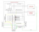
Existing.jpg

Proposed Diagram - (Link for large image)
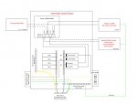
Proposed.jpg


Q1. Circuit Breakers configurations - 60 Amp feed from Main power panel; 110 Amp total on sub-panel. To help reduce the total amps on the sub-panel, I'm thinking of the following:

Slot 1: 30A single pole -> replace with a 20A single pole; supports GFCI outlet, which is rarely ever used
Slot 2: tandem 20A -> replace with a single 20A single pole; supports 2 LED pool lights
Slots 3/4: 20A double pole -> replace with 20A double pole with GFCI; supports the pool pump at 10.9 amps

Any thoughts on this setup?

Q2. THWN wires from the power source looks like it slightly melted/burned at one point (1-2" of sheathing). What is the best way to handle this?

Q3. New Circupool RJ45 SWG will connect to the timer on terminals #2, #4 (load #1 and load #2 on the Intematic timer). It will share the double pole 20 Amp circuit breaker with the pool pump and gas heater. I can't find the max amp draw from the gas heater, but I can't imagine it being high. Will it be ok to run the SWG, pump, and gas heater on the same circuit?
 
Last edited:
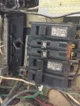
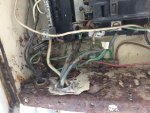
Below are some pics. Clearly you can see I need to replace the panel!

Q2: I'm thinking of using butt connectors, wire nuts, or I may be able to drop the control box down a couple inches. I have to believe rain/sprinklers caused all this damage. I have since removed the sprinklers, but we haven't had any issues in the 7 years we lived in this house.

IMG_4288.jpg

IMG_4287.jpg
 
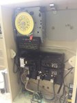
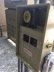
I didn't receive any comments, but I wanted to share that I completed the Intermatic timer control panel replacement!

A1: Circuit Breakers configurations - 60 Amp feed from Main power panel (8 AWG). This control panel is broken up into 2 buses - Phase A and Phase B. I decided to reorder my breakers as follows:

Slots 1A/2A: 20A double pole -> replace with 20A double pole with GFCI; supports the pool pump at 10.9 amps
Slot 1B: 30A single pole -> replace with a 20A single pole; supports GFCI outlet, which is rarely ever used
Slot 2B: tandem 20A -> replace with tandem 20A single pole; supports 2 LED pool lights (decided to keep the other breaker for a future LED landscaping light project!)

A2:THWN wires from the power source looks like it slightly melted/burned at one point (1-2" of sheathing). This was my major concern. I have a couple of theories of what caused the excessive heat - 1) the previous owner installed high powered landscaping lights and used the pools' control panel/timer as the power source. I'm thinking he overloaded the circuit, which caused the burning. 2) water from the sprinklers/rain got into the box (see the rust above). However, the other wires are fine so I'm still thinking the landscape lights were the culprit.

Either way, I was nervous, but cut back 2" of the wire and the 8 AWG wire appeared to be in a great shape!! Whew .. so i ended up dropping the control panel slightly and I've been running 220V through it over the last 2x days with no issues.

A3. New Circupool RJ45 SWG will connect to the timer on terminals #2, #4 (load #1 and load #2 on the Intematic timer). It will share the double pole 20 Amp circuit breaker with the pool pump and gas heater. I called up Circupool and they said that the RJ-45 uses about 1 amp. I ordered a check valve to prevent backflow/damage to the heater. Hopefully will have that in a few days and get my SWG running!


Anyhow .. here is a picture to show the job as complete! One other thought, someone connected the bond wire from the heater and pump to the common ground bar in the previous panel. I disconnected that as the pool bonding and ground are suppose to be separate systems. I just haven't had the time to update my diagrams above. After I powered up the control panel, pool lights, and pump, I wet the concrete, coping, and danced in/out of the pool and am still alive to tell about it. :p

IMG_4378.jpg IMG_4389.jpg
 
Nice job.

One Thing to keep in mind is #8 thwn is rated at 50 amps. But that decreases as distance increases. How far is the panel from the timer? also how many amps is the SWG? do you run your pump for 4 or more hours at one time?
 
JZA1736, thank you for the response. You bring up a great point on the #8 THWN. It was a detail i glossed over since i didn't touch the 60A main circuit breaker feed into the subpanel nor the wiring. I went back and remeasured the thickness and it looks more like #6 THWN, which is rated at 65 amps. The distance between the panel is about 150'. This should be good, correct?

Finally, I was told by the manufacturer that the SWG uses 1 amp.

View attachment 68313
 
The markings on the wiring is not legible. It could pass for a #6 or and #8. However, I took a part the panel and measured the thickness. I'm pretty sure it's #6 THWN.

On a spectate note, I added in a second timer to run my SWG. I'll be sharing that project on a future post.
 
Thread Status
Hello , This thread has been inactive for over 60 days. New postings here are unlikely to be seen or responded to by other members. For better visibility, consider Starting A New Thread.