Hi! Just found this site after what I thought was going to be an easy change out. For the record, I am a good troubleshooter, but, basic understanding of how the timer works.
I have a 240 single mode pump and a 240 booster pump and Lighting. My original Tork 1104NC was installed

Pole 1 has one leg of the 220 (please excuse my terminology...)..the second wire on the 1st pole is going to a nearby GCFI plug that goes out to the lights (you can see the common going through in the back). I believe that the second pole has the second leg of the 220. On the switch side, I believe the 3rd pole has the supply side for the both pumps and the 4th pole is the Load sides for the pumps.
This timer had worked for some time, but, eventually died and I got tired of going out and switching it on and off. Looking online, I found the Intermatic P1353ME and thought this sounded like a good product. I am going to confess to being a bit naive here...I thought that on the P1353ME I would simply hook up the 220 Legs coming from the Box to 1 & 2, the Pump to 3 & 4 and the Booster to 7 & 8 and then set the timer to Mode 3 and I would be done in no time.
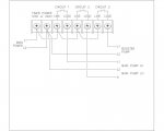
I guess you figured out that I learned that wasn't how it works. I did, however, find this image on the interwebs:

And I wired my intermatic based on that:

So, what I have the two legs from the box on 1 & 2, I put the Supply side to the Pump on 2 "B" and a Jumper from "1B" to 3. 4 has the Load to the pump. And, the motor comes on and appears to run happily. I thought I was on my way. I tried to duplicate this by jumping "3B" to 7, putting the supply line of the booster pump to 4B and the Load on 8. And, of course, nothing happens. At this point, I try several more combinations but nothing works.
It dawns on me at this point that I may be missing a concept that is preventing me from understanding why this isnt working.
I am all for calling out an electrician for helping get this installed, but, I'd really like to learn why this didn't work. It was a fun weekend, got to spend time outside, got to replace some conduit that snapped on me. And I am happy I have the pump running.
Any insights...or, what should I be asking the electrician for?
Thanks All!
Chuck
I have a 240 single mode pump and a 240 booster pump and Lighting. My original Tork 1104NC was installed

Pole 1 has one leg of the 220 (please excuse my terminology...)..the second wire on the 1st pole is going to a nearby GCFI plug that goes out to the lights (you can see the common going through in the back). I believe that the second pole has the second leg of the 220. On the switch side, I believe the 3rd pole has the supply side for the both pumps and the 4th pole is the Load sides for the pumps.
This timer had worked for some time, but, eventually died and I got tired of going out and switching it on and off. Looking online, I found the Intermatic P1353ME and thought this sounded like a good product. I am going to confess to being a bit naive here...I thought that on the P1353ME I would simply hook up the 220 Legs coming from the Box to 1 & 2, the Pump to 3 & 4 and the Booster to 7 & 8 and then set the timer to Mode 3 and I would be done in no time.
I guess you figured out that I learned that wasn't how it works. I did, however, find this image on the interwebs:

And I wired my intermatic based on that:

So, what I have the two legs from the box on 1 & 2, I put the Supply side to the Pump on 2 "B" and a Jumper from "1B" to 3. 4 has the Load to the pump. And, the motor comes on and appears to run happily. I thought I was on my way. I tried to duplicate this by jumping "3B" to 7, putting the supply line of the booster pump to 4B and the Load on 8. And, of course, nothing happens. At this point, I try several more combinations but nothing works.
It dawns on me at this point that I may be missing a concept that is preventing me from understanding why this isnt working.
I am all for calling out an electrician for helping get this installed, but, I'd really like to learn why this didn't work. It was a fun weekend, got to spend time outside, got to replace some conduit that snapped on me. And I am happy I have the pump running.
Any insights...or, what should I be asking the electrician for?
Thanks All!
Chuck


