- May 27, 2021
- 1,396
- Pool Size
- 17000
- Surface
- Fiberglass
- Chlorine
- Salt Water Generator
- SWG Type
- Pentair Intellichlor IC-40

I assume this is the inlet and outet of the heater? Can you show all plumbing before it and just after?

I will check this again tomorrow. When I opened that valve all the way, I noticed the pressure on the gauge near the pump dropped by 5 psi, but I did not check the filter pressures. I only looked at the flow meter and I did not notice any change in the flow rate. I will try this again and will be sure to check to see if the filter pressure rises.If the filter pressure changed but the flow meter did not, there might be an issue with the flow meter.
Correct. I am moving that valve all the way to the right. When I do that the pressure in the guage right after the pump (shown in the pic) drops by about 5 psi.This is the valve you are changing, correct?
Yes. All of the plumbing before and after the inlet and outlet of the heater is in the "pit". There is a lot of plumbing down there and I'm not always sure what I'm looking at, but I will try to get some pics.I assume this is the inlet and outet of the heater? Can you show all plumbing before it and just after?
No. The vertical pipe you see with the closed valve on it is capped and not functional. I believe that was connected to the old erosion feeder. (We used to use trichlor, but changed to liquid chlorine last year.)Is there another pipe coming off that valve (i.e. 3-way)?


Here are a series of pics showing the plumbing into and out of the heater (as best as I could capture it). Hopefully this gives you a good idea of the setup.Can you show all plumbing before it and just after?


Because the filter pressure is changing, there definitely is a flow rate change. It just may not be registering on the flow meter for some reason.Here are before and after pics with that red valve partially open and fully open along with the filter pressures in each position. There was no change in the flow rate.

Not sure you are looking at it correctly. One fiter is reading about 21 psi before and after adjusting that valve. The other is reading about 18 before and after adjusting the valve. It's not going from 18 psi to 21 psi.Because the filter pressure is changing, there definitely is a flow rate change. It just may not be registering on the flow meter for some reason.
Yes, I believe that is the pump. Would a pic of the label on the pump help to confirm?Is this the pump that you have:
I don't understand all of this, but I think you are saying the pump should be putting out 180 gpm. Is there a way to test the flow meter? There was a BW flow meter (the old type that the State doesn't allow anymore) installed in front of the current one temporarily, but we were getting the same reading form that one. H2 Flow Controls (the company that sells the FlowVis) also has a digital flow meter. Does anyone have experience with those? I want to get a digital flow meter installed anyway because the way the FlowVis is installed it is very hard to read. However, I don't know how those digital flow meters work. Would they possibly give an accuarte reading.... even if the one currently installed is bad..... or does the digital meter just pick up what the FlowVis is reading?The original pump PSI and suction in-hg you posted were 30 PSI and 9" HG respectively. This would indicate a total head loss of close to 80' of head. From the pump curve, flow rate is right at 180 GPM (DMJ curve). There may be an issue with your flow meter.
From what I can see, you have no bypass and metering system. All the water your pump is putting out is running through the heat exchanger and this is limiting your flow to what the heat exchanger can handle. It’s a bottleneck. Basically the bypass would be a pipe with a valve in the middle connecting the inlet and outlet pipes of the heater. You would also want valves on the inlet and outlet side of the piping before the heater but after the bypass. You can then tweak all three valves to restrict inlet and outlet flow to the heater to allow it to heat most efficiently while tweaking the bypass to increase flow back to the pool.Here are a series of pics showing the plumbing into and out of the heater (as best as I could capture it). Hopefully this gives you a good idea of the setup.
Is there anything there that looks like a metering valve? Let me know if you see anything that could be restricting flow or have any questions. Thanks.
View attachment 647931View attachment 647932View attachment 647933View attachment 647934View attachment 647935View attachment 647936View attachment 647937View attachment 647938View attachment 647939View attachment 647940
That is correct but only if you can confirm that the link I posted is the pump you are using.I don't understand all of this, but I think you are saying the pump should be putting out 180 gpm.
Not very easily.Is there a way to test the flow meter?
It depends on the flow meter. Venturi style meters like you had before are the worst and can easily be thrown off by placement.There was a BW flow meter (the old type that the State doesn't allow anymore) installed in front of the current one temporarily, but we were getting the same reading form that one. H2 Flow Controls (the company that sells the FlowVis) also has a digital flow meter. Does anyone have experience with those? I want to get a digital flow meter installed anyway because the way the FlowVis is installed it is very hard to read. However, I don't know how those digital flow meters work. Would they possibly give an accuarte reading.... even if the one currently installed is bad..... or does the digital meter just pick up what the FlowVis is reading?
 www.troublefreepool.com
www.troublefreepool.com
www.troublefreepool.com
 www.blue-white.com
I think this configuration may exist, but I'm not 100% sure. I'm going to take some better pics of this section of the plumbing and post again so you can see it a little more clearly. Then, you can tell me whether this is the configuration you are referring to. Does a metering "valve" look different or function different than a regular ball valve?Basically the bypass would be a pipe with a valve in the middle connecting the inlet and outlet pipes of the heater. You would also want valves on the inlet and outlet side of the piping before the heater but after the bypass. You can then tweak all three valves to restrict inlet and outlet flow to the heater to allow it to heat most efficiently while tweaking the bypass to increase flow back to the pool.
I will post a pic of the label on the pump. Hopefully, that will confirm that it is the same one that you posted.That is correct but only if you can confirm that the link I posted is the pump you are using.
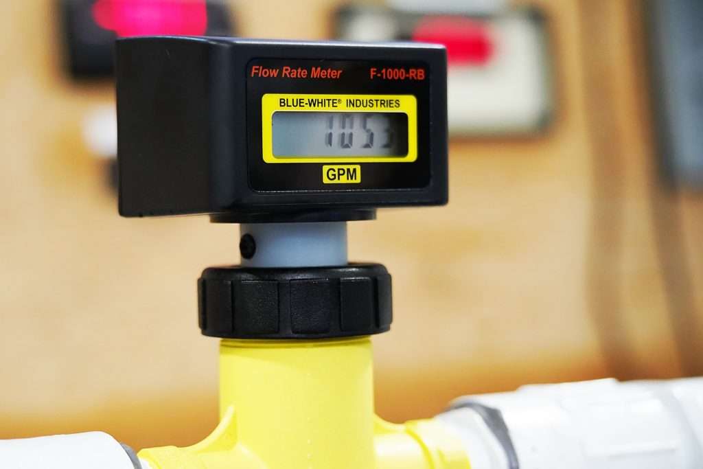
We definitely need a digital flow meter because the placement of the FlowVis flow meter in the pipe makes it very difficult to read. I'm assuming this flow meter would be a replacement for the current flow meter.... not an add-on to the system, correct? Does anyone have any experience with this type of flow meter? If we replace the current flow meter with this one and we get approximately the same reading (120 gpm), then we could definitely rule out the flow meter being the cause of the low flow rate, correct? I'm trying to rule out the simple things.... like a bad flow meter or valves not properly set before we start investing in bigger fixes. The proposals from the pool company that I posted earlier range from $5,000 to $14,000, so we want to be sure we are fixing things that are the real source of the low flow rate... not spending money on things that are unnecessary, i.e., new filters?????Paddlewheel Flow Meters - Blue-White Industries
Accurate flow rate measurements are critical to ensuring the fluid control process runs efficiently. Blue-White’s digital paddlewheel flow meters provide an accurate, safe, and economical method of measuring flow.
That is correct but only if you can confirm that the link I posted is the pump you are using.

The valves are not special, they can be any style. It’s just how the arrangement is setup that allows for metering and bypass.Does a metering "valve" look different or function different than a regular ball valve?
