There are many assumption in FEA and CFD analysis. To make best use, typically a correlation needs to be made to a physical test to get potential accurate result. A more typical use of FEA and CFD analysis is a comparison between 2 or more simulations to determine if the results are as expected and how they differ or from each other (does the change give the expected improvement and is it of a reasonable magnitude).
I am using OpenFoam which many companies and universities use and there are numerous validation studies that I have duplicated to make sure I am taking the right factors into account. Plus for every simulation a mesh sensitivity study is done to make sure the mesh is not influencing the results.
Also, I started off with straight pipe matching results from Darcy-Weisbach to get a calibration point for at least the pipe. Then moved on to match single fitting head loss from minor loss tables such as this one.
Minor loss in PVC and CPVC fittings expressed as equivalent length of straight pipe.

www.engineeringtoolbox.com
And both the 90 and 45 were pretty close to those numbers so this was not done in a vacuum. One thing that I have discovered is the minor losses differs between sources and sometimes, significantly so I don't a lot of people have bothered to confirm these losses.
I also used the CAD drawings from the manufactures so the geometry would be accurate. It turns out there are some differences between manufactures in terms of the geometry as well as head loss.
However, it is difficult to find anyone who has done this type of measurement but Pond Magazine had an article that did a measurement comparing 45s to 90s but the link is not broken for that so I don't know if they retracted that or what happened. However, I do plan on testing this and have a rig setup ready to go.
CFD analysis for water is pretty forgiving, but if flow rate/velocity, pressure, temperature, surface roughness and other factors are not accurate results can be easily skewed and possibly misleading.
PVC is very smooth and even Darcy-Weisbach equations do not show a significant variance with roughness or temperature, for typical pipe and pool.
One thing to look for is how well the simulation can predict cavitation and how it deal with it. Does you model take into consideration the glue squeeze out or gaps present when a pipe is not full in a socket, the diameter differences between pipe and fittings?
As for the glue joints, I am actually using a chamfer for the transitions as it is easier to converge the analysis.
Keep in mind that the intent here is not to directly match watch any one installer might have done only to see if certain configurations can make things better or worse. So more of a comparison study.
It is possible to get accurate results but it will take a significant amount of time and effort accurately modelling the system and figuring out pump curves (i don't know how you would model a sand filter other than vastly simplify it).
I have already created models for most plumbing items. The spreadsheets are in my signature. Pretty much any piece of plumbing can be modeled (first order) as a parabolic because of the V2 term in the head loss equations. In fact, the regulatory agencies have adopted this approach as well and all now using parabolic plumbing curves, in addition to head curves, to model pump performance on different plumbing. The models that I have create have been validated/calibrated many times over the last couple of decades with my own as well as other members plumbing measurements. So they can usually get pretty close to reality.
The proximity of the fitting to one another is not likely a likely a major contributor to the flow/pressure issues here. If it is, it's also because the flow is to high for the system and that is a bigger issue.
At this point I would not expect it to be either. Even in the case of the 2x45s, the difference was a reduction in head loss of only about 10% so not very much influence even if you double it.
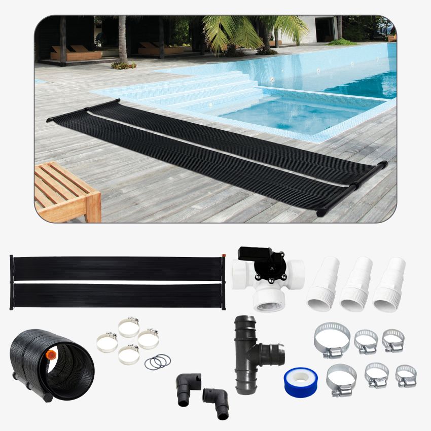
A booster pump for the solar or setting the valves to create a differential pressure between the inlet and outlet of the solar circuit are what can be done. A venturi could be be used to get the differential but I am not sure it would be easily sourced or fit within the plumbing. The booster pump is the more expensive fix but also probably the best for making best use sun, the other option should have values to prevent the solar panels from working as radiators when the sun isn't on them.
I agree that a booster is the less desirable option.

")