Pool Light Timer

Nov 13, 2020
11
Phoenix, AZ
Hey everyone, I have a WPC-2 control box for my pool. It used to have a remote control that operated the pool light, but that gave up the ghost. I want to add a second timer to just control the pool light to come on and go off at the same time everyday. A smart timer would be even better, but I don't want to get greedy here. Anyway, I can't find another timer that looks like the other one anywhere, unless I'm missing something. According to the SRSmith manual, it's a WPCTC but when I google that, it looks like its just the time clock and not the surround that goes in the box.
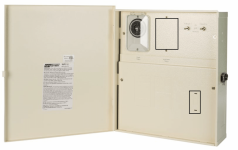
This is what my box currently looks like (except some breakers on the bottom half):

Screen Shot 2021-11-20 at 9.01.37 AM.png
And I want it to look like the one in this video (or a smart timer):

These are the timers I can find, but as you can see, it's missing the surround and cover that the one in the box has.
Screen Shot 2021-11-20 at 9.06.19 AM.png

Can anyone help me with this?
 
I don't know of any product like the one you're looking for. But, we ended up adding a WiFi "smart switch" to control our pool/spa lights. I don't know if one would fit in your control box, but ours works great. It obviously makes things more complicated to set up and run than the mechanical timer you mentioned, but there would be a few ways to have the automatic on/off happen through an app or home automation system.
 
We put it in the control box. There was already a cutout for a standard sized electrical "device" in the side of our panel. This is the switch we used:


We needed 2 switches since we wanted to control each light. If you just have 1 light, you might just want the single switch version. Hopefully your control box is fairly close to your WiFi router, so that you wouldn't have trouble connecting.
 
It would be worth trying. The main thing you need is for the screw holes to be aligned, so that you can mount the switch. You will be able to cover the switch with a standard cover like you have in your house (which will likely be included with the smart switch). You could buy a cheap regular switch at Home Depot and see if the holes align...if they do, the smart switch would fit too.
 
hmmm, there are two spots for a cutout on my panel still, I wonder if I can put a switch in one of them:
Yes, but your switch may have problems receiving a strong enough WiFi signal through the metal enclosure. You won't know until you hook up the switch and test. In my case, it works using a Kasa HS200 switch. I've used a variety of brands and Kasa perform best.

Your other option is to mount a switch using the knock out on the side of the box and use a plastic outdoor switch/outlet cover. You may need to drill a couple holes to mount the switch. Here are a couple pics of my box that show two switches mounted inside and an outlet on the outside.
20211123_115709.jpg
20210317_092026.jpg
The switches inside my panel were not mounted correctly. The proper way to mount switches inside is to use "standoff posts" that screw into the back panel of the box behind the knock-outs. The screws shown in the photo below are removed and replaced with the posts.
20180317_155656.jpg
The switch is than screwed into posts. This keeps the switches in place when you remove panel so you don't have to deal with a tangle of wires attached to the panel. I'm not sure if SR Smith uses the same mounting posts as Intermatic.

Your best bet is to use the side mount.
 
Unfortunately I already am using the side mount for an outlet, which is in use otherwise I would get rid of it. I'm handy enough to wire up a switch or outlet in my home where I know which wires are which, but in the panel, the lighting wires go to the remote module and a toggle switch. My first priority is to eliminate the remote module and then figure out the smart switch wiring....
 
Presuming that the side outlet you have installed is a GFCI, your lights are likely powered by the load side of that outlet (so that the light(s) are GFCI protected) via the timer and/or remote. You could just connect the new WiFi switch the the load side of the GFCI outlet (you'll need to connect both the "hot" and neutral wires so that the switch can draw power to run its "smarts"), connect the switch grounding wire to the grounding bar in the panel, and connect the wire leading to the light(s) to the load side of the switch.
 
Here's what I got going on:
(and before you ask, I turned off the pool sub panel breaker at the main)
  • I removed the remote receiver and brain which is why you see all these connector hanging out.
  • The purple line is the White Neutral wire from the bus bar to the light
  • The red line is the Red wire coming from Circuit 1 to the yellow wire connector then black wire to the light
  • The panel you see hanging down has two toggle switches on it, the left one is Circuit 1 (light). The orange wire was for the remote which is no longer connected.

IMG_0264.jpg
 

Enjoying this content?

Support TFP with a donation.

Give Support
Thread Status
Hello , This thread has been inactive for over 60 days. New postings here are unlikely to be seen or responded to by other members. For better visibility, consider Starting A New Thread.