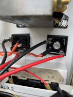
ProLogic blowing 20A fuse.

One other thing I just thought of is that K1 controls the power from the yellow leads to the orange leads so if you are not forcing the K1 relay on (i.e. turn on the SWG), there will be no voltage on the orange leads.

You could just do continuity checks on the rectifiers to determine if they are ok.

One more check, with the SWG cord removed Black and Red wires off board, what is the resistance between the top two pins (L & R) of the white SWG cord socket.
 
Last edited:
One other thing I just thought of is that K1 controls the power from the yellow leads to the orange leads so if you are not forcing the K1 relay on (i.e. turn on the SWG), there will be no voltage on the orange leads.

You could just do continuity checks on the rectifiers to determine if they are ok.

One more check, with the SWG cord removed Black and Red wires off board, what is the resistance between the top two pins (L & R) of the white SWG cord socket.
 
Top two pins are closed on the relay as expected less that 1 ohm.

Going to check the rectifiers individually next. Hopefully, I can beat the daily afternoon T-storm here in FL!
 
Top two pins are closed on the relay as expected less that 1 ohm.
The top two pins are for the + & - so they should have infinite or very high resistance. They may be charging the filter capacitor so wait for a while as see if the resistance rises.

[EDIT] Negate this. Again, if the SWG is not energized, then K2 or K3 will not be switched so there will be a short. It is difficult to check for shorts on the board if the relays are not energized as in operation.

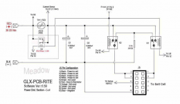
BTW, that schematic is for the AquaRite which is slightly different than the ProLogic. The relays are labeled differently and there is no thermal limiter.
 
Last edited:
Well, in any case, she is up and running! Thanks James and Mark for all your help. You guys have been awesome.

I selectively checked the rectifiers. James must have xray vision. I found half of the bridge on the left is bad. (I don't see the funny coloration here that showed up in the pic though. I had bright sun behind me and may have been reflection from the orange wires ;)) I just swapped the orange AC wire to the opposite side and everything seems to be working with no blown fuses (yet).

I guess I will need to order some new rectifiers and just replace both of them at this point before I have a fire or something. Where do you guys recommend I get them?

My existing salt cell appears to be working again now. I already ordered a new SG cell and will replace it anyway due to it's age. I'm guessing that the black tarry stuff that is dried on the ground under the cell can't be a good sign?

Mark
 
Since the relays are single pole, double throw, I would think that they would feed opposite poles when not powered and they would reverse poles when switched.

So, both get power or neither gets power.

So, unpowered or powered, there should not be a short.
 
In the ProLogic, the K2 & K3 relays are driven separately. So when one is on, the other is off. You can trace the conductors. The + & - are connected to the same terminals on each relay. So in order for one to send + to one lead and the other relay - to the other lead, only one can be energized at a time.

You can use these bridge rectifiers:


Enjoying this content?

Support TFP with a donation.

Give Support
One other thing I just thought of is that K1 controls the power from the yellow leads to the orange leads so if you are not forcing the K1 relay on (i.e. turn on the SWG), there will be no voltage on the orange leads.
I thought that one yellow connected to one orange through the 20 amp fuse and the other connected directly through the board without going through anything like a relay?

What is the correct way to test the rectifiers?

From what terminal to what terminal and what should the reading be?
 
Since the relays are single pole, double throw, I would think that they would feed opposite poles when not powered and they would reverse poles when switched.

So, both get power or neither gets power.

So, unpowered or powered, there should not be a short.
OK James all good. I went back and rechecked it while powered up and I get infinite resistance now. Hmmm. I unplugged the cell and the check system light comes on with the no cell warning. When plugged back in it finds it and the light goes off. So, all looks like it's doing what it should now. Thanks again for your help.
 
  • Like
Reactions: JamesW
I thought that one yellow connected to one orange through the 20 amp fuse and the other connected directly through the board without going through anything like a relay?

What is the correct way to test the rectifiers?

From what terminal to what terminal and what should the reading be?
No, it connects them through the K1 relay. If you look at the traces, the path after the fuse goes to K1. The other K1 connection goes to the orange terminal.

With bridge rectifiers, continuity can be measured from one terminal to an adjacent terminal and there should be full continuity (low resistance) in one direction and infinite resistance in the other direction. That is usually good enough but here are the details for each diode in the bridge:

+ Term (+meter) to either AC Term (-meter) inf ohms
+ Term (-meter) to either AC Term (+meter) 0 ohms
- Term (+meter) to either AC Term (-meter) 0 ohms
- Term (-meter) to either AC Term (+meter) inf ohms
 
  • Like
Reactions: JamesW
Can you check the current diagnostic readings?

Go to the diagnostic screen, note the readings and then press the + button to reverse the polarity.

When the new numbers appear, see what they are.

Then, press + again and note the new readings.
 
No, it connects them through the K1 relay. If you look at the traces, the path after the fuse goes to K1. The other K1 connection goes to the orange terminal.

With bridge rectifiers, continuity can be measured from one terminal to an adjacent terminal and there should be full continuity (low resistance) in one direction and infinite resistance in the other direction. That is usually good enough but here are the details for each diode in the bridge:

+ Term (+meter) to either AC Term (-meter) inf ohms
+ Term (-meter) to either AC Term (+meter) 0 ohms
- Term (+meter) to either AC Term (-meter) 0 ohms
- Term (-meter) to either AC Term (+meter) inf ohms
Thanks Mark you answered James' question before I could get back to him.
James, you can also use the method above in the diode mode on the DMM.
Look for +/- 0.5-0.7 V drop across a good diode anything else it's bad.
 
  • Like
Reactions: JamesW
View attachment 348835

Can you check the current diagnostic readings?

Go to the diagnostic screen, note the readings and then press the + button to reverse the polarity.

When the new numbers appear, see what they are.

Then, press + again and note the new readings.
25.79V 7.06A
86 deg 3000 ppm
+
25.78V 7.54A
86 deg 3200 ppm
+
25.78V 7.29A
86 deg 3100 ppm
 
To get the performance percentage of the cell in each polarity, divide the instant salinity reading in each polarity by the actual salinity reading.

For example, if the instant reading is 3,300 ppm and the actual salinity reading is 3,300 ppm, then the salt cell is working at 100%.

However, if the actual salinity was 3,800 ppm, then the performance percentage is 86.8%.

Anything over 75% is acceptable.

At75%, or lower, in either polarity, it's time to consider replacing the cell.

The instant salinity in both polarities should be about the same (+/- about 200 ppm).

You need to be really sure about the actual salinity reading.

You need to use a K-1766 salt test kit or a calibrated meter.

K-1766 Taylor Salt Test
 
Wow you guys are amazing.

On a side note, if the new cell give higher salt reading, say actual salinity is 3,000. Cell reading it is 3,600. Does that mean cell is working at 120% (is that a good thing?)
To get the performance percentage of the cell in each polarity, divide the instant salinity reading in each polarity by the actual salinity reading.

For example, if the instant reading is 3,300 ppm and the actual salinity reading is 3,300 ppm, then the salt cell is working at 100%.

However, if the actual salinity was 3,800 ppm, then the performance percentage is 86.8%.

Anything over 75% is acceptable.

At75%, or lower, in either polarity, it's time to consider replacing the cell.

The instant salinity in both polarities should be about the same (+/- about 200 ppm).

You need to be really sure about the actual salinity reading.

You need to use a K-1766 salt test kit or a calibrated meter.

K-1766 Taylor Salt Test
 

Enjoying this content?

Support TFP with a donation.

Give Support
Thread Status
Hello , This thread has been inactive for over 60 days. New postings here are unlikely to be seen or responded to by other members. For better visibility, consider Starting A New Thread.