My new automation system.

Nice, you always manage to find the best looking stuff, including the DIN rail mounts.
Wait until you see my v2! :D I found this thing called busbars. So basically you just wire it once to a bar that connects all the breakers together at the top or bottom. So your wiring is reduced. I have two little connectors that need to come in and then I'm going to break it all down and re-wire. Should look beautiful when it's done!
 
v2 is done. I was never happy with the way I had everything laid out so I decided to have one last dance with the old girl.
I made some changes a long the way as well.

Hardware
1. Switched to a hat that could handle 5v inputs natively, one of my main issues is I don't program and I don't do breadboards. The Sequent Microsystems board could only handle 3.3v max for my sensors but if you look around all the sensors are based on 5v. So I found a MCP3208 based ADC hat on Tindie that does 5v. Now my sensors are plug and play.

2. I found some tri level terminal blocks to give myself more room The 3 rails aren't connected to each other. Also, 2 of the rails don't even go through to the other side making them smaller, so you get some room vertically in addition to horizontally. You can pass a common voltage across all the adjacent blocks by using a screw down busbar. So add 0v/5v with 2 wires and it's passed along to all sensors via the busbar. The sensor signal wire is the only one that has a hole on both sides. One to go to sensor, one to go to MCP3208 hat on Pi. I also was able to use them for power distribution to my power supplies. With ground, common and hot to each device all housed in a single terminal block.

3. I was also never happy with all the wire runs I required to hookup my circuit breakers. I found something called busbars and it allowed me to reduce my wire running by A LOT. I feed the main power into the busbar and it hits all my breakers across the 2 phases of 120v with a single connector. It also allowed me to pretty up the look a bit with less wires.

4. I decided that despite my children being complete and utter turds sometimes, I love them. I recently read a news story (WARNING! SAD!) about a girl who got electrocuted by pool lights. So I decided I'd add a GFCI to the circuit that goes to my lights to protect my cute little investments. (Seriously, they're gonna grow up and support me, since my first two didn't...). It was a major PITA to find a 240v DIN rail GFCI circuit breaker but I managed to do so. It's not the same style (UL439 vs UL1077) as the rest of my breakers though. To maintain the busbar system, I will have to replace them all and UL439 breakers are double the cost of UL1077 breakers but I'll do it because they're worth it.

5. As @Katodude pointed out, I was likely going to run out of power with my 1amp 24VAC if I tried to run more than one actuator at a time. For the day when I eventually get my actuators, I've installed a 72VA (100VA peak) 24VAC transformer so I can run all 3 actuators at the same time and still have enough power to run my relay coils.

That's it on the hardware side. I still have to add my Stenner power, Dolphin power, and current sensors back and I thought I had a dead pi when I put it all back together, but turns out the sdcard just got corrupted. I copied the files back onto it and it booted up like a champ. I also still need to find a reliable method of mounting it to the post so I can have my 30 year old sawhorses back. My youngest son misses them.

I don't think I'll do too much with the hardware side anymore. I'm finally (almost) happy with it. But I have a few more things for the software side.

1. Complete my "Buy the chlorine reminder" subroutine. I added a button to the menu system that resets a chlorine replenished timer. A 5 gallon jug lasts me 2 weeks and 2 days since my Stenner always pumps the same amount. So I hit a button and it starts a 2 week timer and then it sends me emails to go buy some more. I have to figure out why I'm not getting the emails and make it more robust. Potentially, I'll include a whole suite of reminders.

2. Figure out why Alexa integration stopped working. I think it's because there's a 25 device limit and I added my security panel to Alexa but I'm going to need to fiddle with it to confirm that.

3. Get an intelliflo and start this whole process over again with RS-485 signally and probably nodejs-poolcontroller integration.

4. I also added my Node-RED code to github so if this thing ever goes Tango Uniform on me again I'll have a backup.

And because this is TFP, this isn't a post without pictures, so here she is. I put some lipstick on the pig!


controller v2-paste.png
 
Nice. I'm waiting for my pump to die so I can pick up an Intelliflo. The RS-485 adapters to interface the pump with a pi start as low as 6.99 on amazon. So it's pretty cheap to get into experimenting with nodejs-poolController. That would also allow you much more control over your pump vs just using the relay speed settings.

I've started keeping my flows on github.
I have the usb to rs485 adapter...and the cable that came with the Intelliflo. Not quite sure how to connect those two devices. Once I figure that out, I have nodejs-poolController installed on my Pi, so can start playing with it.

If anyone has any pointers on nodes-poolController, I would love to hear them. I've read all I can but some of the notes from the GitHub are a bit over my head. Would love to find a tutorial somewhere.

I don't have an intelliflo yet but it doesn't look too bad. The RS-485 cable is two wires. Should plug into the two ports on the adapter pi adapter. Then you start the nodejs software with npm start. Then you go to http://yourpiaddress:3000 and you should get a web menu and if all was done right you should have a web page with some info on your pump in it.

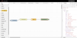
Fortunately, nodejs-poolController let's me run without having the actual unit. On the node-RED side I crafted up something that pulls the data into a formatted Node-RED object that you can and do useful things with. Hopefully it'll be a good starting point for you.

EDIT: Found you could do this all in the http request node. Ignore the nodes in the picture but the output in the debug screen is still the same.

[{"id":"e2a2549c.2e2c88","type":"http request","z":"6b473864.c23c28","name":"pump","method":"GET","ret":"obj","paytoqs":false,"url":"http://192.168.1.58:3000/pump","tls":"","proxy":"","authType":"","x":530,"y":300,"wires":[["119ddde4.7445f2"]]}]

EDIT #2: Made it slightly more useful. Flow will now pull pump status, stop and start the pump.

[{"id":"6b473864.c23c28","type":"tab","label":"Intelliflo","disabled":false,"info":""},{"id":"119ddde4.7445f2","type":"debug","z":"6b473864.c23c28","name":"","active":true,"tosidebar":true,"console":false,"tostatus":false,"complete":"payload","targetType":"msg","x":770,"y":360,"wires":[]},{"id":"e2a2549c.2e2c88","type":"http request","z":"6b473864.c23c28","name":"Pump Status","method":"GET","ret":"obj","paytoqs":false,"url":"http://192.168.1.58:3000/pump","tls":"","proxy":"","authType":"","x":550,"y":300,"wires":[["119ddde4.7445f2"]]},{"id":"bf477c60.2458","type":"inject","z":"6b473864.c23c28","name":"","topic":"","payload":"Push button to go","payloadType":"str","repeat":"","crontab":"","once":false,"onceDelay":0.1,"x":360,"y":300,"wires":[["e2a2549c.2e2c88"]]},{"id":"3301db19.05e2e4","type":"http request","z":"6b473864.c23c28","name":"Run Pump","method":"GET","ret":"obj","paytoqs":false,"url":"http://192.168.1.58:3000/pumpCommand/run/pump/1","tls":"","proxy":"","authType":"","x":550,"y":360,"wires":[["119ddde4.7445f2"]]},{"id":"3f05f67e.766aba","type":"inject","z":"6b473864.c23c28","name":"","topic":"","payload":"Push button to go","payloadType":"str","repeat":"","crontab":"","once":false,"onceDelay":0.1,"x":360,"y":360,"wires":[["3301db19.05e2e4"]]},{"id":"88f0911b.cc0e6","type":"http request","z":"6b473864.c23c28","name":"Stop Pump","method":"GET","ret":"obj","paytoqs":false,"url":"http://192.168.1.58:3000/pumpCommand/off/pump/1","tls":"","proxy":"","authType":"","x":550,"y":420,"wires":[["119ddde4.7445f2"]]},{"id":"a2b7462a.e23dd8","type":"inject","z":"6b473864.c23c28","name":"","topic":"","payload":"Push button to go","payloadType":"str","repeat":"","crontab":"","once":false,"onceDelay":0.1,"x":360,"y":420,"wires":[["88f0911b.cc0e6"]]}]
 

Attachments

  • nodered intelliflo test.png
    nodered intelliflo test.png
    38.7 KB · Views: 30
Last edited:
I don't have an intelliflo yet but it doesn't look too bad. The RS-485 cable is two wires. Should plug into the two ports on the adapter pi adapter. Then you start the nodejs software with npm start. Then you go to http://yourpiaddress:3000 and you should get a web menu and if all was done right you should have a web page with some info on your pump in it.

I hooked up my pump to the rs-485 adapter, but am getting nothing via serial, so not really sure what to do to troubleshoot. The web address above populates, but there is no data and it says "never" in the last connection. Wondering if it's possible I got a bad usb to serial converter?
 
I hooked up my pump to the rs-485 adapter, but am getting nothing via serial, so not really sure what to do to troubleshoot. The web address above populates, but there is no data and it says "never" in the last connection. Wondering if it's possible I got a bad usb to serial converter?
I'd check the logs first. Or the console. When you run it by hand it should put the output to the console.
I'm assuming you're running from 'npm start' Are you getting any errors? I get this:
21:20:12.041 INFO Your version (5.3.0) is the same as the latest published release.
21:21:11.086 INFO Serial port recovering from lost connection.

Because I don't have an intelliflo.
I’m getting the exact same response. However, I do have an intelliflo lol. I’m not getting anything from the console but do see the serial adapter being recognized by the pi. Wasn’t able to get anything from my Mac either, so I’m wondering if my adapter isn’t working or possibly some other user error.
 
I’m getting the exact same response. However, I do have an intelliflo lol. I’m not getting anything from the console but do see the serial adapter being recognized by the pi. Wasn’t able to get anything from my Mac either, so I’m wondering if my adapter isn’t working or possibly some other user error.
I found this manual. Looks like yellow is +, green is -. You want to hook up while power is killed to the pump.

I also found this statement:
Note: For the IntelliFlo VS+ SVRS to accept commands from IntelliComm, the pump must be in the “Running Schedules” mode (LED above the Start/Stop button lit).

If you've done all that then... ?‍♂️
 
  • Like
Reactions: arielpool
Wow, this is a fantastic project, congrats! I'm living vicariously through this post as I can't get my wife to let me mess with the old Jandy system I installed 5 years ago. I'd love to try something similar with esp 32.

Keep up the great work!

Chris
 
  • Like
Reactions: cmc0619
I’m getting the exact same response. However, I do have an intelliflo lol. I’m not getting anything from the console but do see the serial adapter being recognized by the pi. Wasn’t able to get anything from my Mac either, so I’m wondering if my adapter isn’t working or possibly some other user error.
I also just checked over at the nodejs-poolcontroller gitter space. The very last question by someone was how to hook it up.. Here was their response

See page 18/19. Red/black is power/ground (you don't need that). And Yellow is DT+; Green is DT-. You can hook those two up and if the packets can be read you are good... if not, just reverse those wires. You won't short anything out.

Hope this helps!
 

Enjoying this content?

Support TFP with a donation.

Give Support
Wow, this is a fantastic project, congrats! I'm living vicariously through this post as I can't get my wife to let me mess with the old Jandy system I installed 5 years ago. I'd love to try something similar with esp 32.

Keep up the great work!

Chris
Thanks! Check out @jonpcar build too. His UI interface is beautiful and he's got some really cool things going on with meters for chlorine and acid levels too. Also, @segalion is doing one too. And @Katodude is just starting on his. We really should have a sticky with all the DIY projects in here! :D
 
  • Like
Reactions: arielpool
I found this manual. Looks like yellow is +, green is -. You want to hook up while power is killed to the pump.

I also found this statement:
Note: For the IntelliFlo VS+ SVRS to accept commands from IntelliComm, the pump must be in the “Running Schedules” mode (LED above the Start/Stop button lit).

If you've done all that then... ?‍♂️
I’ve done all that but I did hook up the adapter while the pump was running. What is the consequence of that?
 
4. I decided that despite my children being complete and utter turds sometimes, I love them. I recently read a news story (WARNING! SAD!) about a girl who got electrocuted by pool lights. So I decided I'd add a GFCI to the circuit that goes to my lights to protect my cute little investments. (Seriously, they're gonna grow up and support me, since my first two didn't...). It was a major PITA to find a 240v DIN rail GFCI circuit breaker but I managed to do so. It's not the same style (UL439 vs UL1077) as the rest of my breakers though. To maintain the busbar system, I will have to replace them all and UL439 breakers are double the cost of UL1077 breakers but I'll do it because they're worth it.

Hmm, this gives an idea. I have two GFCI 120v circuit breakers. Would it make sense to wire each side of the hot 240v entrance with one of the breakers?
 
Hmm, this gives an idea. I have two GFCI 120v circuit breakers. Would it make sense to wire each side of the hot 240v entrance with one of the breakers?
I don't think you could do that. The problem is they have to both trip at the same time. That's why the 240v breakers are always tied together. There may be some other innards that are related to that. I don't think this would be a good idea.

It would be a good idea to protect your whole panel this way though with a legit 240v GFCI breaker though. The problem there is, I don't know if they have breakers that go that high. I don't know about your panel but mine is 30A and the breakers I've found are only good up to 20amp. You could probably find one in a DIN rail format but it'd be super expensive most likely. Like 2-300$. If you have a main breaker box that's feeding your pool it'd probably be cheaper to replace that traditional breaker with GFCI (becoming the new standard NEC recommendation anyway) as it would be a lot cheaper.

I was also looking for a surge protector for my panel but decided instead to just do a whole home unit that protects my main breaker, and by extension my pool controller, instead.
 
Hi Cliff, @cmc0619
I may have missed it in your posts, but would you mind linking what 120 and 240 relays you are using. I've looked all over Automation direct and have found a very large variety of relays but haven't found the ones that seem to look the same visually. Just trying to make sure I'm not missing something and if there is a specific reason you picked the ones you did. i.e. slim, or other feature.

My plan is to control the larger relays with a Pi HAT relay board (still deciding there too). Just for the SWG and heater.
 
Last edited:
Hi Cliff, @cmc0619
I may have missed it in your posts, but would you mind linking what 120 and 240 relays you are using. I've looked all over Automation direct and have found a very large variety of relays but haven't found the ones that seem to look the same visually. Just trying to make sure I'm not missing something and if there is a specific reason you picked the ones you did. i.e. slim, or other feature.

My plan is to control the larger relays with a Pi HAT relay board (still deciding there too). Just for the SWG and heater.

Sure thing! They're the 782 model. Socket, relays, and MOVs for relay protection when switching inductive loads.

I picked them because they were rated for 15Amps. If/when I get my Intelliflo I'll have to head into contactor territory

For lower currents and to save rail space you can also use the slim relays. You can use these jumper poles to link common wires to reduce wiring as well. I probably should've used these for my pool lights instead of the 782s but I guess there's something to be said for keeping everything the same as well. If you're really tight on space I found a dual slim relay as well. I picked one up. It's pretty tall so didn't use it.

A few of us are using the Sequent Microsystems board (on sale here) with good success. I've looked far and wide and have yet to find anything else with 8 relays in a hat format.

Thank you. That's really helpful. Now that I look at them they totally match. These are what I was looking at but for some reason they didn't look like the ones in your pictures. Perhaps from scrolling through HUNDREDS of relays on the Automation Direct site, everything blurred together.

I'm exactly on track with your suggestion. The SM Hat for the smaller relays and (future) sensors and the 782 relays for my heater and SWG. I don't need relays for the pump. I have a CicruPool variable speed pump and the add on automation board they offer just takes 5v inputs to activate the pre programed speeds. The pump will stay hardwired to it's GFCI breaker.

Thanks again for the info. That was the last piece I was trying put together for 'phase 1' of my project. Phase 2 will be temp sensors to better control the heater and acid injection. It's been so interesting to see how different folks have approached the DIY projects.
 

Enjoying this content?

Support TFP with a donation.

Give Support
Thread Status
Hello , This thread has been inactive for over 60 days. New postings here are unlikely to be seen or responded to by other members. For better visibility, consider Starting A New Thread.