Thanks a lot for the above posts. Questions for you: Does changing viscosity (fluid resistance) versus changing plumbing resistance have the same impact on the pump's power consumption?
When pumping a different fluid there are two factors to take into account, the fluid's viscosity and specific gravity. A pump's head curve does not change with either viscosity or specific gravity and this is one of the reasons that the head is used instead of PSI. PSI changes with specific gravity but head doesn't. However, the plumbing curve is affected by viscosity so an increase in viscosity will increase the head loss in the plumbing and change the operating point of the pump thereby reducing the flow rate. The energy consumption is related to the hydraulic HP which in turn is related to specific gravity of the fluid so the energy demand from the impeller will change slightly with the type of fluid.
Now what if you increase the viscosity of the fluid, and make the pump move oil instead of water. What happens to the pump's wattage, given a fixed RPM, etc ?
Oil has a lower specific gravity (lighter) than water so for a given head and GPM, the power required to pump it is actually less than water. But because oil has a higher viscosity, the head loss in the plumbing will be higher for a given flow rate. Therefore with the same plumbing and pump, the oil will have higher head loss, lower flow rate and much lower energy consumption than water.
I am starting to figure something out. If you have an increase of plumbing head in a system given a single RPM, less actual water will get to the pump's impeller. Thus the pump actually works LESS. This is why wattage falls as plumbing head increases (ie you hook a pool vacuum up to a line).
That is pretty much correct although I might say that the flow rate through the pump is reduced rather than water is prevented from getting to the pump. Nothing prevents water from getting to the pump except for the water ahead of it. In other words, the flow rate.
Also with regards to lower energy use for lower flow rates, this is mainly true for pool pumps but not for all pumps in general. Some very high head pump designs, think water towers, have an inverted power curve. But this because the lift has to be so high. The energy consumption of a pump is related to the hydraulic HP which is the product of head AND GPM. So if head increases at rate higher than GPM decreases, then the pump will use more energy for lower flow rates but again, this doesn't apply for pool pumps.
Also unrelated question (actually more related). I've been measuring power consumption via a wrap around multimeter, and only reading current. I have accurate amp readings. Do I plug watts or VA into this spreadsheet? They aren't the same, assuming this pump has a power factor of something else than 1.0 (lets say .9).
So most importantly, what is the power factor on these intelliflo pumps?
The power factor should be very close to 1.0. This is because a VFD first converts the AC to DC and then runs the DC into gate arrays which create the PCM waveform. So the load presented to the AC line is basically real. However, the lines feeding the actual 3-phase motor may have a power factor but that will not translate back to the AC line waveforms because of the AC to DC conversion.
Because a VFD uses PCM, there are current pulses that end up on the AC supply line which might affect how the meter measures the current. If the VFD has sufficient filtering, this should not be a problem and you should still get a fairly accurate measurement. But the only way to tell for sure is to put a scope on the current probe.

 I mistook the head for GPM. BRain fault on my part. Mas985's chart matches mine.
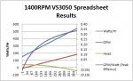


") .
.

