Black and Decker Pump automation?

dfwmj

Active member
Feb 4, 2024
28
Texas
Pool Size
20000
Surface
Plaster
Chlorine
Liquid Chlorine
I described the setup in some detail here:


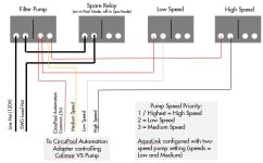
Also attached a wiring diagram of how I setup the relays. Hope this helps.
Sorry to revive the old thread but I am trying to do what you did and could really use assistance. I only have one open relay on my board, will need to buy one, and would love to understand how the panel used/supports a dual speed on a single relay or was that a separate/special relay that jandy makes to support 2 speeds. My spa vales kick over automatically in spa mode and want to keep all of that working and follow the VSP rules of being always on.

Moved from here.
1000002536.jpg1000002535.jpg1000002533.jpg1000002534.jpg
 
Last edited by a moderator:
@Rancho Cost-a-Lotta and @hexabc may have thoughts.

Check this out in the meantime.

 
, and would love to understand how the panel used/supports a dual speed on a single relay or was that a separate/special relay that jandy makes to support 2 speeds.
Jandy Aqualink uses a special 2 speed relay for 2 speed motor pumps…

 
Jandy Aqualink uses a special 2 speed relay for 2 speed motor pumps…

Thanks I saw that and was guessing I was going to need to procure one of those, however dis not see that in the previous post.
 
I don't know much about your automation system, but @HermanTX or @PoolGate may be able to help.

In the linked thread, @gkw4815 used a Calimar VS pump with an automation interface adapter.

Best of luck!
Thank you! I was going to pickup the black and decker VSP, simular to his setup and the same automation adapter. Hence I was very interested in the final build and wires. If it comes down to it, is it common for pool repair folks to come out and help with wiring? 😆
 
Thanks I saw that and was guessing I was going to need to procure one of those, however dis not see that in the previous post.
You do not use that relay with the automation adapter.

Have you read the Automation Adapter Installation Manual?
 
You do not use that relay with the automation adapter.

Have you read the Automation Adapter Installation Manual?
Ah ok yes I have but it mentioned running the wiring to multiple relays and sadly I do not have room on my board for that. But I saw the aqualink panel had a dip switch for a multiple speed pump and was hoping I could leverage that. I am new to all of this bit willing to learn, sadly have a dead pump and looking to get it swapped soon. The B&D vsp is on the way.

I will give that manual another read. I appreciate you calling that out.
 
If you have iAqualink or a RS system with REV O or greater it may have been better for you to get a Jandy VS pump that can connect to your Aqualink using RS-485 control.

Without available relays you will not be able to use the automation adapter.
 
If you have iAqualink or a RS system with REV O or greater it may have been better for you to get a Jandy VS pump that can connect to your Aqualink using RS-485 control.

Without available relays you will not be able to use the automation adapter.
I would have loved to do that but at 3 times the cost, could not justify it. So I can free up a relay by removing my booster/cleaner pump as I ise a Robot now anyway. So that would offer 2 available the the existing for the filter pump now, if it is not doable with just 2 relays.
 

Enjoying this content?

Support TFP with a donation.

Give Support
Note that the automation adapter has worked for some while others have had problems getting it working.

2 relays will give you a 2 speed pump.
 
I have mine set up with three relays for three speeds, but you could get by with two speeds. If you're using the automation adapter, you don't need the special Jandy two-speed motor relay. You just need two regular relays, one for each speed.

To be honest I've forgotten the details of how I set up my automation adapter to iAqualink interface, but IIRC I set the Aqualink DIP switches to "fool" Aqualink to think I had a standard two speed pump. Once I did this, and programmed the schedules correctly, everything worked. The pump would run in low speed most of the time but would kick to high speed when scheduled or when the spa was activated.

On the automation adapter side, you need to wire it so that the low speed relay has higher priority than the high speed relay - ie, if both relays are on, the pump will run on low speed mode.

Hope that helps some... I'd recommend reading the Aqualink manual for your particular panel to make sure you're setting the DIP switches correctly.
 
Without available relays you will not be able to use the automation adapter.
I agree. You need what @gkw4815 did:

If you decide to keep your new B&D, you can use it with the pump's control panel scheduling. Later you can consider installing independent wifi relays, possibly adding a safety current switch, sensing the pump current and disconnecting SWCG when no current is detected.
 
Thanks @gkw4815 and everyone else for the feedback. So looking at my panel photos, does the existing replay for the filter pump count as one, the I could re-purpose the cleaner pump relay, and add the 3td in the spare slot?

I am just worried about ensuring the pump can prime as needed and the roll over spa switching still works.
 
If that's the case, you can add a relay and control a total of three speeds if you want.

Your new VS pump should be wired to continuous 240v power, and the previous "Filter Pump" relay should be used to control your medium speed (if you use three speeds) or high speed (if you use two speeds).

Attached schematic shows how I wired mine up...you can ignore the 120V SWG wiring and Spare Relay, which are not applicable unless you're also using a non-Jandy SWG.

If you "trick" Aqualink into thinking that you have a two-speed pump, wiring it this way will satisfy the following requirements:
  • Pump will run at medium speed whenever you're in spa mode
  • Pump will run at medium speed for a couple of minutes to prime, anytime it's being started after having been switched off
  • Pump will not run whenever your automated valves are switching between pool and spa mode
 

Attachments

  • Relays.JPG
    Relays.JPG
    83.6 KB · Views: 15
Thank you! I was going to pickup the black and decker VSP, simular to his setup and the same automation adapter. Hence I was very interested in the final build and wires. If it comes down to it, is it common for pool repair folks to come out and help with wiring? 😆
For a fee, sometimes. Giving advice opens a company to more liability than actually doing the work. When one does the work, he uses his/her experience, knows that it has been done the way it would have been instructed, and tests before leaving. Giving advice does not mean that it is going to be followed and if not, in case of a claim, the courts/arbitrators side with the customer 99% of the time, even if the instructions were correct, because the customer always ;) follows them to the letter. Ask an attorney. For 30+ years that is the advice that has been given by ones who litigate for the insurance that most pool techs have.
 
  • Like
Reactions: Newdude
If that's the case, you can add a relay and control a total of three speeds if you want.

Your new VS pump should be wired to continuous 240v power, and the previous "Filter Pump" relay should be used to control your medium speed (if you use three speeds) or high speed (if you use two speeds).

Attached schematic shows how I wired mine up...you can ignore the 120V SWG wiring and Spare Relay, which are not applicable unless you're also using a non-Jandy SWG.

If you "trick" Aqualink into thinking that you have a two-speed pump, wiring it this way will satisfy the following requirements:
  • Pump will run at medium speed whenever you're in spa mode
  • Pump will run at medium speed for a couple of minutes to prime, anytime it's being started after having been switched off
  • Pump will not run whenever your automated valves are switching between pool and spa mode
Thanks again. What replay or model did you buy or was used for the other speeds. For example I see 3HP relays. Fo i need those for the 3HP B/D pump? What is confusing to me, is in your diagram it looks like 4 relays, but maybe that is just my misunderstanding.

On my panel I have filter pump (red), booster (blue), and the free one (orange).

Does red align to your medium, blue low and my spare/orange high?
 

Attachments

  • 20240208_181853.jpg
    20240208_181853.jpg
    143 KB · Views: 3
  • image000000.jpg
    image000000.jpg
    252.1 KB · Views: 3
Last edited:
3 hp relays = the relays are rated to handle enough amps to power a 3hp single-speed pool pump. You could say these relays are "overkill" for low-voltage applications like switching pump speeds on an automation adapter, but they'll get the job done.

You can get the Jandy 6581 relay or a generic equivalent.

In my wiring diagram, ignore the 4th relay ("Spare Relay") - I use this to switch off my SWG whenever my pool is in spa mode. I use the other three relays to control the pump speeds.

The color-coding in your diagram basically matches how mine are set up. Filter pump relay becomes your medium speed, and two others are used for low and high.
 
  • Like
Reactions: dfwmj
3 hp relays = the relays are rated to handle enough amps to power a 3hp single-speed pool pump. You could say these relays are "overkill" for low-voltage applications like switching pump speeds on an automation adapter, but they'll get the job done.

You can get the Jandy 6581 relay or a generic equivalent.

In my wiring diagram, ignore the 4th relay ("Spare Relay") - I use this to switch off my SWG whenever my pool is in spa mode. I use the other three relays to control the pump speeds.

The color-coding in your diagram basically matches how mine are set up. Filter pump relay becomes your medium speed, and two others are used for low and high.
Thank you for taking the time. Much appreciated
 
I went with a simpler route to "automate" my new Black and Decker VSP which is only supplying a new water feature on our pool. Since its only supplying that, I dont need to control the different speeds - all I needed was on/off which on VSP seems to not be so simple to control. The reason I purchased a VSP was because I dont need a lot of water and running it almost at its lowest speed is sufficient and it replaced a very old single speed pump that was hooked up to our previous water feature.

Basically I removed the plastic control box and PCB that has the motor controller in it (the one sitting on top of the pump). I then removed the control board from the housing (6 small black screws) and soldered a wire to each side of the "Start/Stop" button on the PCB (a little fiddly), so essentially touching these 2 wires is the same as pushing the button. Next I found the 5v and GND pins on the white connector that is used to connect the board to the actual pump. They are labled on the PCB. So I now have power and a means to replicate turning the pump on/off. Final part of the control was I purchased this from Amazon (shown below)

1711391954450.png

I then connected the receiver module (on the left) to these new connections. The Power to the Power wires from the PCB and the Common and Normally open wires to the two wires from the Start/Stop switch. I finally drilled a small hole in the plastic housing of the motor control to enable the extended antenna to stick out. The module is so small that there is plenty of room in the controller housing - I wrapped it in insulation tape and reassembled the original motor control PCB back onto the pump and powered it up, testing everything still worked. So I still have the original controller which still functions as before, just with the extra electronic relay board connected, all nicely housed in the original controller housing sitting on top of the pump motor.

For the transmitter part (the module on the right of the picture) , all it needed was a small box, a 9v battery and a push to connect button. This I mounted on the wall near to where the pool is (vs. where the pump is located) again drilling a small hole for the antenna.
I then set the speeds to what I required on the pump (all 4 the same). So pushing the remote button effectively is the same as me walking to the pump and pushing the Start/Stop button on the pump itself.
So far seems to work like a charm.

I unfortunately have not taken any pictures of the wiring - need to do that sometime - but hope you get the general idea.
 
Last edited:

Enjoying this content?

Support TFP with a donation.

Give Support