First let me say that I've leaned a lot about pool maintenance from TFP and finally made it through last year without one outbreak of dreaded yellow algae!
My Aqualink controller stopped communicating with my indoor control panel--probably due to a power surge. Even though the surge protector light is on, I doubt it still works. Another item to replace.
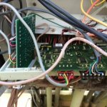
I decided I might as well upgrade to the iAqualink and I watched a video of someone upgrading their board. It looked very simple--all plug and play. I ordered the upgrade Aqualink 2.0-RS after confirming compatibility. I turned off the power and pulled the old PCB out. I am seeing a couple of things that weren't in the first video. I did find another set of video's of a guy upgrading a system which was more in depth. I have a small board attached on the left side with a small bar screwed over the square area of the bezel. I also have a 4 pin connector attached to the red 4-pin "receiver" on the upper left of the board. I am a rabid DIY girl but am not well versed in electronics so please forgive my lame terminology... I'm not quite sure what these are. I think the 4 pin connection may be the indoor panel and/or the Spa side control. Got that from the last video I watched. If correct, the guy said it didn't matter which 4 pin connector was used. The wireless unit would connect to the remaining red 4-pin "receiver". My PCB also has a black 6-pin connector which I think is the Spa side control so the 4-pin may just be the indoor panel??
Can anyone tell me what the small board on the left is in pic? Is the 4-pin red connector actually the indoor panel connection? Do I need it since the upgrade will not operate it? I thought the second 4-pin connector on new PCB was for variable speed pumps. I don't want to blow the new board so thought I'd ask for advice before continuing.


