Troubleshooting a Compool CP3000 - jet pump not getting power

NC,

When you measure 240 volts you must measure between the two hot legs (L1 and L2 to get 240 volts.. As you have found out, measuring between L1 to ground and L2 to ground will show about 120 volts on each.. EVEN if one leg has no voltage.. this false reading is due to the pump being in the circuit.

The problem is that you are missing either L1 or L2..

Go to the main circuit 240 breaker for your automation and measure L1 to L2.. If you get 240, then measure the voltage coming into the automation and see if you get 240 volts.. If you do, then move on to the Aux relay that is wired to the 'bad' pump. Test the output of the relay, L1 to L2.. At one of those spots you should be missing 240 volts. It could also be an open wire, but that would be very odd. Most likely a relay or bad breaker.

Thanks,

Jim R.
Thanks. To clarify, the measurements I mentioned above are without the pump in the circuit.
I do have normal voltage for the other 2 pumps. Is it typical that all the pumps run off the same 240V breaker, or would they have separate breakers?
 
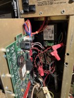
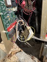
can you post the picture from 8 without markings as well as a photo of the full pad showing all conduits?
Here are some more pics. One thing I discovered: the white wires leading into the black block measure 35V between them. They seem to lead out to the old Water Witch auto-fill controller which never worked. the red wires also attached at the same points lead down the right side conduit to two toggle switches (look like light switches). Toggling one of those kills power to the entire control box; toggling the other kills power to the pump. I didn't investigate further, but I bet I can measure the hot side of that toggle switch and see if it has 240 there. i bet it does, as I think it also controls the purple wires coming from the same conduit... and these purple wires lead to the slide pump that does work and does have 240V. I'm beginning to think the old Water Witch is my villan.
 

Attachments

  • IMG_7938 Large.jpeg
    IMG_7938 Large.jpeg
    270.9 KB · Views: 4
  • IMG_7939 Large.jpeg
    IMG_7939 Large.jpeg
    256.7 KB · Views: 3
  • IMG_7940 Large.jpeg
    IMG_7940 Large.jpeg
    278 KB · Views: 4
  • IMG_7941 Large.jpeg
    IMG_7941 Large.jpeg
    271.4 KB · Views: 4
  • IMG_7942 Large.jpeg
    IMG_7942 Large.jpeg
    254.6 KB · Views: 4
  • IMG_7944 Large.jpeg
    IMG_7944 Large.jpeg
    265.4 KB · Views: 4
  • IMG_7943 Large.jpeg
    IMG_7943 Large.jpeg
    287.8 KB · Views: 4
  • IMG_7945 Large.jpeg
    IMG_7945 Large.jpeg
    236 KB · Views: 4
  • IMG_7946 Large.jpeg
    IMG_7946 Large.jpeg
    205.9 KB · Views: 4
Do the 2 reds come from the breaker or the 2 whites? Where do the 2 that dont come from the breaker go ?
Sorry, I buried the answer in the above post. The white ones seem to lead to the Water Witch. The red ones lead down a conduit to a toggle switch, and that switch kills the power to the pump. So I think the red ones ultimately lead to the breaker.
 
The red ones lead down a conduit to a toggle switch, and that switch kills the power to the pump
Do the two reds measure 240V? If not, you'll need to pull the switch and see if you have 240v leaving the switch, if not, is 240V entering the switch? It would not be unthinkable for the ~$8 switch to be the source of the issue from day 1 :sneaky:
 
  • Like
Reactions: NeedCoffee
How many breakers feed the compool panel?
I think 3, but it's hard to tell because the labels are cryptic. One says filter pump, and there are 2 that say booster pump.

Today I disconnected the white wires at the Water Witch and capped them with wire nuts. So the Water Witch is out of the circuit now. no change to the voltages. Then I opened up the toggle switch box and found white corrosion, almost the consistency of shortening or cake icing, all along the bottom of the box. I'm not sure how water has been getting in there since there is no obvious entry point. I cleaned out most of it, but you can see the effects in the pics in this post. I also measured voltage drop across the two switches in the box. The left one with red wires is the circuit of interest. I measure 35V across it when switch is off. The right one (with blue wires) measures 240V when off. So I guess that implies that the switch could be the problem? I'll grab one from HD tomorrow and just try it.
 

Attachments

  • IMG_7948 Large.jpeg
    IMG_7948 Large.jpeg
    222.8 KB · Views: 3
  • IMG_7949 Large.jpeg
    IMG_7949 Large.jpeg
    234.5 KB · Views: 3
  • IMG_7947 Large.jpeg
    IMG_7947 Large.jpeg
    269.7 KB · Views: 3

Enjoying this content?

Support TFP with a donation.

Give Support
The left one with red wires is the circuit of interest. I measure 35V across it when switch is off
I can't tell from the photos, are these double pole switches (4 wires plus ground to each switch )
If the problem is the switch, when disconnected from the switch, the two wires coming from the conduit below should measure ~240v.
 
I can't tell from the photos, are these double pole switches (4 wires plus ground to each switch )
If the problem is the switch, when disconnected from the switch, the two wires coming from the conduit below should measure ~240v.
They are both single-pole. The left one for example has 2 red wires and one green ground. Nothing on it's left side. I didn't get a chance to troubleshoot today. Will try tomorrow.
 
They are both single-pole. The left one for example has 2 red wires and one green ground. Nothing on it's left side. I didn't get a chance to troubleshoot today. Will try tomorrow.
so how are you testing voltage? With a single pole switch (which is not compliant as there is still power to the pump when the switch is off from the other leg) you should be going (based on how i am understanding your wiring) red on the switch to red pass thru
 
so how are you testing voltage? With a single pole switch (which is not compliant as there is still power to the pump when the switch is off from the other leg) you should be going (based on how i am understanding your wiring) red on the switch to red pass thru
In the above, I was measuring voltage across the switch when it was off. So on the right side one, with the blue wires, when the switch was off I measured 240V. On the lefthand switch, with the red wires, the voltage was 35V with the switch off. Very odd.

But I think I did find the issue. The breaker didn't seem to be fully on, like it had tripped but only moved a little. I switched it completely off and back on a few times, then went back to the controller to measure voltage... and got 240V at the pigtails (with the pump circuit on). So I guess the issue was with the breaker itself. Next I guess I'll put the pump back in the circuit and see if the breaker holds.
 
  • Like
Reactions: Ahultin
Woot! Bubbles! It finally worked. I guess the breaker was the culprit all along, though I think the pump needed to be rebuilt and likely was the root cause of the failure originally. Thanks very much for your help, @Ahultin !

And for anyone searching for pump rebuild info: The motor rebuild cost me $480 and the brand new wet end was $260. Not really cheap, but about $500 cheaper than buying a new variable-speed Pentair pump, which for this application is overkill.
 

Attachments

  • IMG_7956 Large.jpeg
    IMG_7956 Large.jpeg
    410.8 KB · Views: 1
  • Love
Reactions: Ahultin
Thread Status
Hello , This thread has been inactive for over 60 days. New postings here are unlikely to be seen or responded to by other members. For better visibility, consider Starting A New Thread.