The Arduino - Intex SWG
- Thread starter New2Me
- Start date
You are using an out of date browser. It may not display this or other websites correctly.
You should upgrade or use an alternative browser.
You should upgrade or use an alternative browser.
- Jul 16, 2019
- 691
- Pool Size
- 20000
- Surface
- Vinyl
- Chlorine
- Salt Water Generator
- SWG Type
- Hayward Turbo Cell (T-CELL-5)
I just went through this thread, and have no idea what's happening. But it's all pretty amazing!
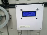
Two weeks in and I'm really happy with my efforts, it's perfect for my needs.
1. Controller wakes-up with the pump via my smart-home system schedule (Samsung SmartThings).
2. Senses water-flow and delays 60-seconds to ensure good water circulation before current is applied to the cell.
3. Regular polarity switching to clean the cell.
4. Low-flow warning w/buzzer
5. Low-salt warning w/buzzer.
6. over-current and immediate shutdown of current through the cell w/buzzer till 60-seconds after the fault clears.
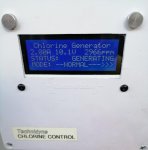
7. Cell current (A) and salinity (PPM) display (updated every ~5-seconds*).
8. All faults and real-time system status clearly described on the display (so nice to know at a glance, exactly what the system is doing).
*Because of nucleation within the cell, caused by water-flow and all the gas bubbles as electrolysis takes place during chlorine production, the actual current drawn by the plates fluctuates very rapidly. To dampen this effect (no pun intended) the software accumulates150 current samples with 5ms pauses between samples, averages and displays the mean (~5-seconds updates). I've found a linear correlation between current drawn across the Intex cell (500PPM through 5000PPM) during tests in my lab (yes, I dunked the cell in 10 different salinity solutions and measured the current at precisely 12V each time). So for our purposes, a simple multiplication factor in software serves as a calibration to convert Mean Amperes (A) to Mean Salinity (PPM). I used the average of 10 readings from my HM Digital COM-80 TDS/EC Meter in the pool as a reference.
Hopefully you enjoyed this read and some of you will venture into the world of Arduino and try this, it takes a really good, inexpensive, saltwater-system and makes it even better IMHO.

Last edited:
- Oct 25, 2015
- 5,809
- Pool Size
- 28000
- Surface
- Plaster
- Chlorine
- Salt Water Generator
- SWG Type
- CircuPool RJ-60 Plus
PieterS
Bronze Supporter
Neat project - I agree, you made a pretty decent inexpensive chlorinator that much better! Wish I knew enough to give this a shot - my main annoyance has been having to keep the pump and chlorinator in sync with their internal clocks - you addressed that nicely.
Great stuff! Trying to understand where some probing is done. There is a part of code 'VcsValue = analogRead(A2); //Read Voltage sensor values' where A2 is connected to the ACS715, but what pin? Would that be pin 6 (FILTER). Pin 7 (VIOUT) will be connect to A0 to do 'AcsValue = analogRead(A0); //Read current sensor values' ?
Thanks!
Thanks!
OneAn9ryN00b
New member
Well, I hope all of you are well and dealing with this pandemic in good spirits, the pool is really proving its worth now.
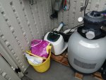
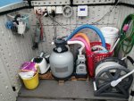
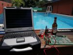
Here's my idea of working from home
Have you posted your code, or supplies used anywhere?
SteveJoiner86
Member
Hello @Cletus ! This is an awsome project. My SWG's control panel died, so I need a solution to replace it. Can you send any information about the electrical connections? (schematic or a simple drawing). Thanks a lot! Regards, István
Thread Status
Hello , This thread has been inactive for over 60 days. New postings here are unlikely to be seen or responded to by other members. For better visibility, consider Starting A New Thread.


