Stenner Pump - Can I add one?

mstang1988

Member
May 3, 2024
16
Austin, TX
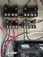
I have a Jandy RS system (I think it’s a 4 but I can’t tell). I want to add a stenner pump. I have 2 relays which aren’t in use but I believe those two relays are only controllable via the filter or AUX1 pump (today the filter and aux1 are unused because I have variable speed pumps). The third and fourth relays are for the lights and blower fan.

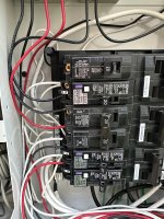
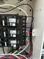
Another problem I see is that that breaker sub panel is fully populated and used (a few of the circuits are connected to my outdoor kitchen). Any suggestions on how to set this up? The unfortunate thing there is no breaker or outlets near the equipment so anything would have to be branched off the circuits.

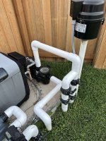
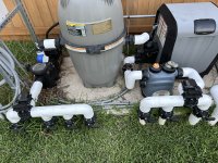
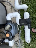
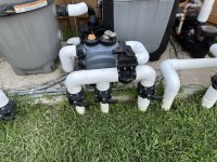
The other challenge I see is finding a place to inject the chlorine off the filter pump. They left no room to add a T anywhere in the layout. On the Aux pump I could add a 2.5” T and then a 1” to 1/4 reducer to inject.

Thoughts on all of this?

IMG_0835.jpeg
 

Attachments

  • IMG_0837.jpeg
    IMG_0837.jpeg
    417 KB · Views: 6
  • IMG_0838.jpeg
    IMG_0838.jpeg
    524.2 KB · Views: 6
  • IMG_0839.jpeg
    IMG_0839.jpeg
    372.6 KB · Views: 10
  • IMG_0841.jpeg
    IMG_0841.jpeg
    760.6 KB · Views: 8
  • IMG_0840.jpeg
    IMG_0840.jpeg
    854.1 KB · Views: 9
  • IMG_0843.jpeg
    IMG_0843.jpeg
    554 KB · Views: 10
  • IMG_0844.jpeg
    IMG_0844.jpeg
    804.3 KB · Views: 11
Welcome to TFP.
The AquaLink is a RS-4 because there are only 4 relays in the box.
Neither of your Jandy VS pumps are controlled by the automation? did you not connect a RS-485 cable from the VS pump to the automation?
If you are switching to Stenner pump injection, will you need to keep that mineral device? Remove that and put a tee in there to inject the chlorine.

Can you explain which each of the breakers are powering? Too difficult to follow all the wires.
 
I just got my multimeter out and set it to DC and checked Aux4/Aux5. They do indeed trigger the 24v outs so I believe the unit is actually an RS6 but with only 4 relays in cabinet.

The Jandy pumps are controlled but do not need the relays as they are smart pumps. I would have to look exactly how they are looked up but for the sake of the 24v relay outs they are open/unused.

Yes, I can absolutely add all the breakers:

Left Side
- Transformer (Power station)
- Lights
- Blower leg 1
- Blower leg 2
- Outdoor Kitchen 1
- Outdoor Kitchen 2

Right Side
- Aux Pump Leg 1
- Aux Pump Leg 2
- Heater Leg 1
- Heater Leg 2
- Filter Pump Leg 1
- Filter Pump Leg 2
 

Attachments

  • IMG_0845.jpeg
    IMG_0845.jpeg
    409.3 KB · Views: 1
I just got my multimeter out and set it to DC and checked Aux4/Aux5. They do indeed trigger the 24v outs so I believe the unit is actually an RS6 but with only 4 relays in cabinet.
Remove that panel that is covering the PCB. Need to see the sockets for all the aux. I think you may have 2 of your relays plugged into aux 4 & 5. not sure until we can view the PCB.
 
For the mineral/chlorine tablet device, I’m open to removing but they didn’t really leave enough room on the PVC to cut it out and add a new fitting so I’m not certain how I would ultimately replace. I know the PVC is 2.5”. What are the fittings called that go to equipment?

if I cut it or just add an extra small setting what considerations do I need to have? Avoid 90’s etc?
 
Remove that panel that is covering the PCB. Need to see the sockets for all the aux. I think you may have 2 of your relays plugged into aux 4 & 5. not sure until we can view the PCB.
There are 8 slots for the relay pins:

1). Not populated
2). Not populated
3). Populated (Blower or lights)
4). Populated (blower or lights)
5). (Aux 4) Not populated but 24v out works
5). (Aux 5) Not populated but 24v out works
 
For the mineral/chlorine tablet device, I’m open to removing but they didn’t really leave enough room on the PVC to cut it out and add a new fitting so I’m not certain how I would ultimately replace. I know the PVC is 2.5”. What are the fittings called that go to equipment?

if I cut it or just add an extra small setting what considerations do I need to have? Avoid 90’s etc?
If you are handy, that ell connected to the 3-way valve going to the pool can be removed with a heat gun. I would remove that mineral device by undoing the unions to give you some working room. Then make a hacksaw cut into that fitting on the 3-way valve. Put a heat gun on it and use a screwdriver and pliers and pull back that pvc fitting. It should come off once you get it all warm and work around the circumference.
Then do the same where the pvc connects to the check valve. Then run new 2.5” pvc from the check valve to the 3-way valve with a tee or whatever you were planning to inject the liquid chlorine.

Suggest your remove the mineral device and practice on that pvc coupling that connects to the half union. Then you can see how it works to heat it and pull it or twist the pvc off.
 
There are 8 slots for the relay pins:

1). Not populated
2). Not populated
3). Populated (Blower or lights)
4). Populated (blower or lights)
5). (Aux 4) Not populated but 24v out works
5). (Aux 5) Not populated but 24v out works
You have 4 black HP relays. They each have a connector that goes to one of the sockets you listed above. So you can only control 4 items with those.

What is the revision of the PCB you have? it is shown on the backside where the CPU is. The newer PCB are set up as RS-8 boards but you are limited by the actual relays in the area below it. You can purchase more HP relays to add to it.
 

Enjoying this content?

Support TFP with a donation.

Give Support
You have 4 black HP relays. They each have a connector that goes to one of the sockets you listed above. So you can only control 4 items with those.

What is the revision of the PCB you have? it is shown on the backside where the CPU is. The newer PCB are set up as RS-8 boards but you are limited by the actual relays in the area below it. You can purchase more HP relays to add to it.
The good news is two of the relays aren’t in use. I traced them back to dangling headers so yeah, I should be good to go on the relays. Aux 4/Aux 5 are controllable and power on. I’ll check the revision.
 
Why? SWCG is by far the most convenient, simple, easy, and inexpensive option for chlorinating your pool. There is upfront cost, but otherwise it's spectacular.
Looks like she is more open to it than I thought. Now I’m trying to cost/price it out. Looks like I would need a new power center as the old one doesn’t have the transformer etc for the SWCG.
 
Looks like she is more open to it than I thought. Now I’m trying to cost/price it out. Looks like I would need a new power center as the old one doesn’t have the transformer etc for the SWCG.
You have a couple of options. Since you have Aqualink then a Jandy SWCG will be able to control the SWCG remotely - if that is important to you. We recommend a SWCG that is 2x your pool volume. So the only option would be the AquaPure 1400. That is what I have.
I purchased a AquaPure 1400 system which includes the SWCG and the transformer. I just connected the AP system to the AquaLink with a RS485 cable and all communicated as it should. You do not need to replace the power center.
The other option is to purchase a 3rd party such as CircuPool which have performed well as used by many members on the forum. It comes with the transformer /control system but lacks integration to an Automation system.
 
Last edited:
Thread Status
Hello , This thread has been inactive for over 60 days. New postings here are unlikely to be seen or responded to by other members. For better visibility, consider Starting A New Thread.