My system is still running this ancient heater from 1987. Physically, the thing is bulletproof, however, we recently had a power fluctuation (main panel lost a leg and the heater system is 240) and it stopped switching on.
I've debugged each component and done some maintenance. Replaced the water pressure switch, replaced the ancient and decayed transformer, and cleaned up the wiring (sanding off corrosion, replacing connectors, etc). It still won't come back to life. Specifically: If I wire up the transformer directly to the S86F pilot/burner box the pilot comes on and it kicks the main valve open and fires right up. The problem is somewhere in the controls. This unit originally had a front panel potentiometer pair that controlled the heat, but I upgraded the entire system to EasyTouch last year (unaffected by power issues), so the actual heater thermostat is now in the automation system. Worked fine until that power issue.
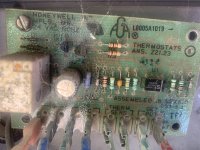
I suspect I wired it up wrong when I reassembled the transformer or the thermostat board fried or a high-limit switch decided to die(have not tested yet)
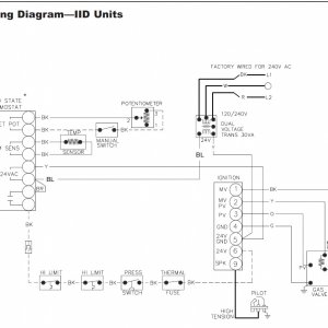
But I need to find a wiring diagram for this old thermostat to make sure I did not do something stupid as my first step. Alternatively, if someone can give me a pointer on bypassing it without bypassing the thermisters or the pressure sensor that would be a great option as well.
Couldn't find anything on Honeywell or Raypaks site.
Here is my unit: Raypak Versa 185B-405B Pool Heaters parts
I've debugged each component and done some maintenance. Replaced the water pressure switch, replaced the ancient and decayed transformer, and cleaned up the wiring (sanding off corrosion, replacing connectors, etc). It still won't come back to life. Specifically: If I wire up the transformer directly to the S86F pilot/burner box the pilot comes on and it kicks the main valve open and fires right up. The problem is somewhere in the controls. This unit originally had a front panel potentiometer pair that controlled the heat, but I upgraded the entire system to EasyTouch last year (unaffected by power issues), so the actual heater thermostat is now in the automation system. Worked fine until that power issue.
I suspect I wired it up wrong when I reassembled the transformer or the thermostat board fried or a high-limit switch decided to die(have not tested yet)
But I need to find a wiring diagram for this old thermostat to make sure I did not do something stupid as my first step. Alternatively, if someone can give me a pointer on bypassing it without bypassing the thermisters or the pressure sensor that would be a great option as well.
Couldn't find anything on Honeywell or Raypaks site.
Here is my unit: Raypak Versa 185B-405B Pool Heaters parts
Attachments


Last edited: