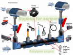
RaspiPool automation | bypass plumbing

Sads

0
Aug 30, 2016
2
BUSSELTON
For anyone who has built/installed a bypass for the sensors, how often do you use the valves if ever?

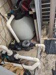
The reason I ask is that my pipes are quite close together and I only have about 150mm length for the sensors. I am therefore considering plumbing it in without the valves because they would not fit.

For the sensors, a 3/4" pipe will run from A to B in second photo, as low as I can get it to the ground. (The teal coloured pump is for solar heating)

Any advice or suggestions most welcome

PXL_20201027_074307780.jpgPXL_20201030_052457783.jpg
 
I have not built a bypass for my sensors. I just have them plumbed directly into my pipes. The temp sensor is very robust and very cheap to replace so not worried about it. The pH sensor is an industrial version so it should handle the pressure. I dont use ORP so not worried.

You can probably live without the valves, just turn the pump off if you want to check or calibrate any of the sensors.
 
  • Like
Reactions: MyAZPool and Sads
I don't know anything about the "expert" part :p, but with all the info I could garner from members here as well as other info I could find on the internet, this is how I chose to plumb my sensor bypass.

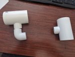
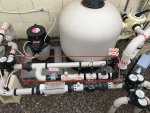
I used a Jandy 3-Way, three 2"s x 2"s x 3/4"t tees and one 2"s x 2"s x 3/4"s tee for the EC probe since the compression fitting that the Atlas Scientific Industrial probe tee inlet and outlet is 3/4" threaded and I wanted 2" slip. So I bought another compression fitting and made my own.

I used a FlowVis to get an approximate idea of water flow through the bypass. Not so much for the gauge but for the clear plastic window as you can see the water flowing and approximate the flow or at least tell that there is minimal water flow through the bypass. This is so the water does not rush past the sensors too fast when pump speed is in vac mode, etc. I do realize that a FlowVis creates some back pressure but all things considered, I did not feel this was too much of a problem.

I chose to install a spare 3/4" threaded tee (which is capped), just in case and for some "future proofing"... Coz cutting into existing plumbing is a real pain.
2020-11-09_07-49-28.jpg

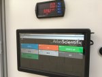
I am reading H2O temp through the EC probe and additionally installed a FAT and humidity sensor in the bottom of my new Automation Enclosure. Also installed an Atlas Scientific Pressure Sender which is giving me Filter Pressure readings.
Eventually I plan on adding an MA tank level sensor and I am currently waiting on an additional card that I will install in my Precision Digital ProVu Water Refill meter that will provide a 4-20mA signal and eventually hope to incorporate that and all of the rest of these sensor readings into the new relayEquipmentManager, which will be integrated with the nodejs-poolController-dashPanel, which I am currently running as my "go to" HMI now for pool automation and control.

Also, I am planning on using one of the Sequent MicroSystems relays mounted on the Raspi Stack to control MA dosing and eventually take MA dosing control completely away from my current IntellipH MA dosing device.

Still lots of work to be done, but I'm getting there (thanks to lots of advice from several members here). This is just about where I'm currently at, when it comes to sensor readings prior to some further pH and EC calibrations.
3892504B-DAAD-4F17-8654-FA428A9C4631_1_105_c.jpeg

r.
 
Last edited:
@MyAZPool I’m replicating your bypass down to the tee (pun intended). Your photo above has my curiosity in the bottom right hand corner what are those devices with the red, blue, and yellow rewind symbols? My pool build is in progress sorry if it’s a basic question.
 
@MyAZPool I’m replicating your bypass down to the tee (pun intended). Your photo above has my curiosity in the bottom right hand corner what are those devices with the red, blue, and yellow rewind symbols? My pool build is in progress sorry if it’s a basic question.
@1900s_Fort_Myers
I think you might be referring to a couple of my Pentair IntelliValve actuators.
Thanks...
r.
 
@Sads
It's been a while since you first posted and you have probably already started or finished your project.
From your picture above it looks like you wanted to run your sensor line between the Return line and the pump suction? Hard to tell with the picture. You will end up with flow from "B" to "A" in that config. Your best to install the sensors pre Cell so that you are measuring your pool water only. You will get some wild readings on your sensors while the Cell is producing.
Can you move your pump over closer to your solar pump to give you more horizontal pipe on the filter inlet?
 
Agree with @CRAD_oz
I believe the preferred location for a sensor/probe bypass manifold or a "Flow Cell" bypass manifold is downstream from the filter and upstream from any heaters, chlorinators, chemical dosing injection taps etc.
This is the location that I selected for my Sensor Bypass Manifold. Directly after the filter but before the heater bypass valve.

2020-11-29_16-48-15.jpg
r.
 

Enjoying this content?

Support TFP with a donation.

Give Support
Thread Status
Hello , This thread has been inactive for over 60 days. New postings here are unlikely to be seen or responded to by other members. For better visibility, consider Starting A New Thread.