- May 29, 2018
- 155
- Pool Size
- 13700
- Surface
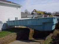
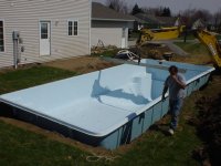
- Fiberglass
- Chlorine
- Salt Water Generator
- SWG Type
- CircuPool RJ-30 Plus
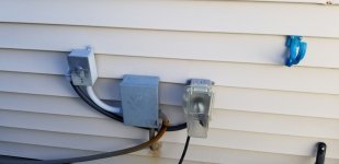
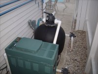
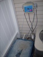
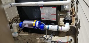
Tried to cram for the upcoming SWG install. I know where I'm putting the cell, flow switch and controller. Planning to get a timer to include with setup (never had one, always 25/7 setup).
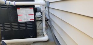
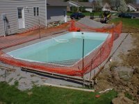
I have an inground fiberglass pool. We have a natural gas heater after the filter. I have a light in a niche which I am sure was safely installed, never have had any issues getting shocked by it. The only other metal in the pool is the old, stainless steel ladder that I am looking to replace with the white coated units, including the grab bar by the steps.
Reading many articles here and posts about anodes for SWG. What is the best design, how and where to put it? Do I need anything to protect the heater or swimmers from any issues with adding the SWG?
")