- Jun 30, 2017
- 388
- Pool Size
- 13000
- Surface
- Fiberglass
- Chlorine
- Salt Water Generator
- SWG Type
- Pentair Intellichlor IC-40
Yesterday, I finally ran the gas pipe for our new PB that was installed in November. I went to turn on the heater and fired right up.
The issue is that I set the heater temp to 104 at the heater control panel and 62 degrees at the IntelliCenter. Water temp was at 58 degrees.
IC called for heat, showed flame symbol and got up to 62 degrees. Then IC showed no more flame and indicated it was not heating anymore.
Went outside a short while later and saw that the water was now 67 and heater still chugging along.
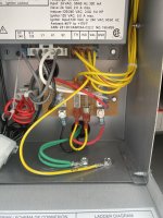
Did some investigating and the electrician wired the gas heat connector (J2) to the spa/common/pool port on the MasterTemp control board.
I’m not even sure how this is even functioning at all, but I digress.
Does this seem like the proper fix:
I assume that I just need to remove the yellow jumper cable in the fireman’s switch and then change the white and red wires from the com port on the heater to the spade terminals on the firemans’s switch. I was thinking of cutting the yellow jumper wire and soldering each half (using the spades) to the white and red wire.
That should give me proper heater control, correct?
Here’s two pics showing the wire as it currently configured (to com port) and the fireman’s switch:


Last edited:


