Hi all,
First time poster here.
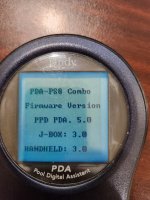
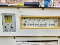
My pool was built in 2010. The Aqualink PDA firmware says 5.0 on the display, so I am assuming that is the version. My old Stealth pump finally died (rusted out) and I have replaced it with the recommended ePump from Jandy (VSSHP270DV2A).
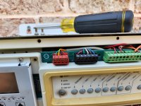
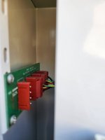
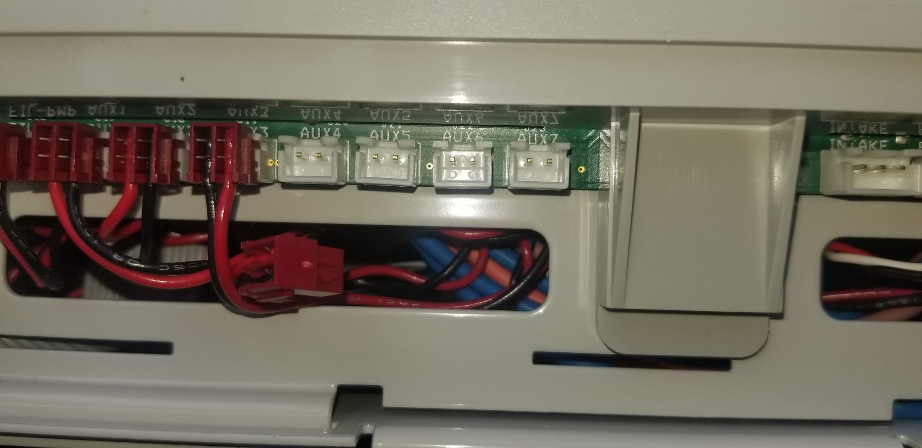
I am fully aware my Aqualink does not natively support variable speed pumps. The power hookup is straight forward, but my question is do I just attach the RS-485 connecter from pump to board? Is there anything else I need to set to get this to run properly?
Thanks in advance.
First time poster here.
My pool was built in 2010. The Aqualink PDA firmware says 5.0 on the display, so I am assuming that is the version. My old Stealth pump finally died (rusted out) and I have replaced it with the recommended ePump from Jandy (VSSHP270DV2A).
I am fully aware my Aqualink does not natively support variable speed pumps. The power hookup is straight forward, but my question is do I just attach the RS-485 connecter from pump to board? Is there anything else I need to set to get this to run properly?
Thanks in advance.