How to; Determine if your Easytouch Com (RS485) can be repaired

jerryt

In The Industry
Nov 25, 2011
264
I have been repairing these Easytouch motherboards.

There is two failures which can occur that takes out the RS485 communication.
The first is failure of the RS485 chip, this I can repair.
The second is failure of the circuit in the processor, this is not repairable.

I found a simple test with a voltmeter which can determine if the processor circuits are good.

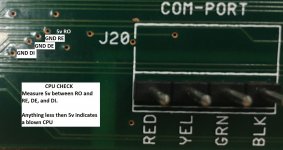
On the back side of the board, while the board is powered, near J20
with the positive lead on "RO" (See attached jpeg),
you should be able to read approximately 5V on "RE', "DE' and "DI" with the ground lead of the voltmeter.
Close to 5V is good, less than 1V is bad.

If your board passes this test then it is worth replacing the RS485 chip if you do not have communication.

Hope this is useful
 

Attachments

  • Easytouch backside RS485 Voltage checks (2).jpg
    Easytouch backside RS485 Voltage checks (2).jpg
    158.3 KB · Views: 93
Hey nice work @jerryt... you could add to your troubleshooting a quick test of current draw (on the 12v supply)... it is often significantly higher when the comm chip is blown. There are around 300? transistors in the chip and usually the ones on the input/output path (DI/RO) will fail... when they fail short the current draw goes way up. The excessive current draw can cause the supply voltage to drop so low that all manner of weird stuff happens.

Have you gotten a board with a dead cpu/microcontroller? I've only ever seen bad cpus on remotes that suffered severe corrosion. When you see the comm enable lines (RE/DE) drop below 5v, check the supply at the 5v regulator output or at one of the 74hc259 logic chips... if it's less than 5 then there's likely a shorted chip that's killing the power supply (e.g. a comm chip, 2803 relay driver, or 74hc259 latch that controls the relay drivers).

If you want to have some really nerdy fun, get one of those cheap $20 logic analyzers off the auction site and connect it to RO/DI/RE/DE pins you pointed out in your image! ;)
 
The damaged CPU's I have all seem to work fine except one or more of the circuits are "Open" DI, DE, etc.

There does appear to be two different failure situations;
Lightning
Shorts of D- or D+ to 15v

PS. I built a tool that desolders the 16 pin screen connector all in one shot
 
Yeah, that darned lightning will often melt or complete burn the chip! I've done a few where the board itself got burned and the traces needed repair 🔥🔥

Would love to see your 16-pin desoldering tool. I wanted to make one too but I haven't been repairing many easytouch boards these days.
 
If you install a RS485 surge protector, it may prevent the Com chip from damage

 
Great info...my RS485 failed end of 2021 after a lightning storm (also took out my Asus Router). Neighbor lost his doorbell camera and some other stuff too. I saw the boards were over $350 back then and just learned to live without the touch controls and comms via app, I ended up just programming my VS pump using the schedules on the pump control panel and manually do stuff like spa and heater controls since. The board still works via manually pushing the buttons and schedule for solar and temp all work fine.
Recently lost 2 out of 3 GloBrites, so getting back into repairs. I was about to pull trigger on new control board until I searched this solution.

I just did that troubleshooting with the board pins on the back side of the RS-485 check. All 5V so I decided to order both recommended chips from Mouser (Digi-Key has them too), I am order 2 and 4 of each in case it happens again or doesn't work on first try since they are cheap.

The Maxim brand is more expensive, MAX1483ESA+T, at $4.50/ea
The Renesas Electronics , ISL81483IBZ, is about $2.30/each
Economy (probaby 1st class evelope) shipping was $3.49.
I'll probably make a detailed YouTube video to document the troubleshoot, desoldering, and repair.
 

Enjoying this content?

Support TFP with a donation.

Give Support
Just fixed my EasyTouch board using info on this thread. Glad I looked again after ignoring the problem and manually using the pump schedule and board since the lightning strike.

Got my RS485 comms working again for $2 chip replacement.

Got a full DIY YouTube video and instructions to troubleshoot and do this fix. Check the description of video for all the part numbers and tools needed.

B71CCD4F-42C2-49FB-BB6E-48AECD2C7692.jpeg
2658A6A5-36C7-4871-AFD9-2A39141296C0.jpeg
 
@vertex if the voltage aren't right and/or the comm chip doesn't fix your board, don't despair, you can still save it... you just need to determine what is broken.

If the controller itself (mc9s12, 112 pin qfn chip) is dead or damaged, it can be replaced and reprogrammed. See this thread:

 
Thread Status
Hello , This thread has been inactive for over 60 days. New postings here are unlikely to be seen or responded to by other members. For better visibility, consider Starting A New Thread.