
I'm trying to put in a new 1.5 HP, 230v 2 speed pump and just want to make sure I have the wiring right before I fry the thing. I'm wanting to wire it with a DPDT switch so I can have the "off" position in the middle.
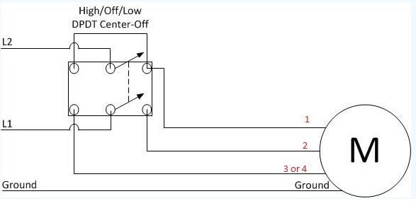
I found this diagram posted in another thread by forum member Ohm_Boy, which seems pretty straight forward:

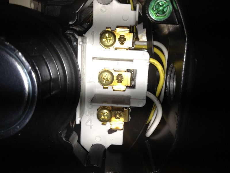
Where I get a little fuzzy is when I look at the diagram on the side is how to convert the "L2", "Low", and "High" in Ohm_Boy's diagram into the 1, 2, and 3or4 listed on my pump:
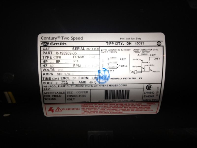
...and this diagram on the side of the pump shows a diagram with what I believe is a DPST, not the DPDT I want to put on:
Now, am I correct in the below diagram in assuming that "L2" is my pump's 1, "Low" is my pump's 2, and "High" is my pump's 3or4? That would have it looking like this:
Thanks in advance!
I found this diagram posted in another thread by forum member Ohm_Boy, which seems pretty straight forward:
Where I get a little fuzzy is when I look at the diagram on the side is how to convert the "L2", "Low", and "High" in Ohm_Boy's diagram into the 1, 2, and 3or4 listed on my pump:
...and this diagram on the side of the pump shows a diagram with what I believe is a DPST, not the DPDT I want to put on:
Now, am I correct in the below diagram in assuming that "L2" is my pump's 1, "Low" is my pump's 2, and "High" is my pump's 3or4? That would have it looking like this:
Thanks in advance!

")