Hayward pump starts, but is noisy and trips breaker.

The piece of grass in the centrifugal switch looks suspicious; almost like someone put it there.

It's possible that it just happened to get there but it's like a one in a million chance.
 
Here is a better look at the centrifugal switch.


Note that either capacitor can fail.

So, you have to check or replace both to rule out a capacitor problem.

I think that the back start capacitor and centrifugal switch only go to the low speed windings.

The debris in the switch might account for the low speed not starting.

The top capacitor is a Run capacitor.

I think that the top Run capacitor only goes to the high speed windings.

If the high speed capacitor is bad, that could account for the high speed not starting.
 
Replace the back capacitor and retry.

If no go, remove both capacitors and the power wires and then test the resistance between L1 and L2, the resistance between L1 and A and the resistance between L2 and A.
 
Is the filter configuration set to 2-speed pump?

Is the low speed aux relay set as filter low speed in configuration?

Based on earlier tests, it seems like both windings were powered at the same time, which might be a configuration error, a stuck relay or maybe a wiring problem.

Since it was working, I suspect that the wiring is probably ok.

So, that would point to a stuck relay or a configuration issue.

You can check the relay by testing for continuity between the terminals on the relay to see if they are open or closed with all power off.

With all power off, the #1 to #2 contacts on the relays should be open.

If both windings were powered at the same time, the motor might be permanently damaged.


I ordered a new capacitor. It is a 161-193 uf 110VAC, so I think you are correct and it's only used on the LO side. Makes me a little skeptical that this will resolve the problem, but much less than the $450 for a new motor. I don't think it could be a configuration thing, unless someone snuck into my backyard and started messing with the controller, but I will check.
 
Maybe a stuck relay?

Check the resistance of the windings and of the relay contacts (with all breakers off) to see what that shows.

Are you getting a voltage reading on the low speed relay contact terminals 2 and 4 while the low speed is supposed to be off?
 
The relay has two top terminals that Omron labels as 0 and 1 where the two small 24 VDC (volts DC) coil wires connect. When the board sends 24 volts DC to the relay coil, it powers an electromagnet and closes the contacts.

There are 4 terminals along the bottom that Omron labels as 2, 4, 6 and 8. See the Omron picture below.

When the coil closes the relay contacts, terminal 2 connects to terminal 4 and terminal 6 closes to terminal 8.

I was calling the bottom row terminals 1,2,3,4 from left to right. Using this description, terminals 1 and 3 get the line power wires. When the coil closes, terminal 1 and 2 connect and terminals 3 and 4 connect.


G7L-2A-TermArrange-v1.jpg


G7L-2A-BUBJ-CB%20AC200%5E240.JPG
 
p1040837-c86a6bd9-1075-4359-9a5e-f452cb39d9de.jpg


You might not be able to see the top coil terminals.

The Aux 2 relay is usually filter low speed.

Using my notation of the bottom four terminals being called 1, 2, 3, 4, terminals 1 and 3 should be powered with 240 all the time and measuring from terminal 2 to 4 should be zero volts when the relay is off.

If you turn off all breakers, and measure the resistance between terminals 1 and 2 and then 3 and 4, there should be no connection. The meter should read O.L, which is open line or over limit.
 

Enjoying this content?

Support TFP with a donation.

Give Support
You can see in the picture that the relay has a little black test button on the bottom that you can push to close the relay.

It should click up and down when you push the button.

Press the test button on the relay with the breakers all off to see if the button is stuck in the up position.

Compare how the button feels compared to the other relay buttons.

If the relay is stuck, you can replace it with one of the ones that I linked to or you can use an existing extra relay if there is one not being used.

For example, if the aux 1 relay is not being used, you can use it to replace the bad relay or move the wires to the aux 1 relay and assign the aux 1 relay to be filter low speed in configuration.
 
I received the new start capacitor and installed. I get the same symptoms.
Looking your notes not the relays, I was trying to figure out the leads on the relay on the motor, housed under the cover. I performed the measurements on the two Relays in use (Filter Pump and Aux 2). The terminals (1 & 2) and (3 & 4) where open (meter read OL).

Aux 2 relay is defiantly the low speed on my installation. It matches your picture in the previous post.

With the system energized, I get 120VAC at terminals 1 and 3 on both relays. I get 0VAC on terminals 2 and 4 on both relays. I think this test indicates that relays are not stuck closed. I suppose one could be inoperative and does not close.

I am attempting to attach a video. Maybe this is more helpful.
Pool Pump Motor Problems - iCloud Photo Sharing
 
poolpumpmains-jpg.174395


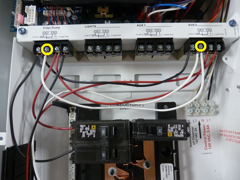
L1 (white) is Hi speed, L2 (black) is common and A (red) is Low speed.

Turn off power, disconnect the wires from the motor and make sure that they are not touching anything.

Turn on power, but don’t activate any speed. Check each line to ground and each line to the other lines. Each wire should test as 0 volts to ground and 0 volts to the other wires.

Starting on High speed, you should have 240 between white and black and 0 volts between black and red and zero volts between white and red.

Starting on Low speed, you should have 240 volts between black and red and 0 volts between white and red and 0 volts between white and black.

Turn off all power.

Next, with the wires still off of the motor, remove both capacitors and test the resistance between L1 and L2, L1 and A, and the resistance between L2 and A.

Do not do anything that you are not sure that you can do safely.

Do at your own risk.
 
Okay. I think we are on to something, but what... I don't know...
The voltage readings make ZERO sense to me. I took them twice.

Off
W <-- 0.90 VAC --> B
R <-- 1.36 VAC --> B
W <-- 0.64 VAC --> R

Lo Speed
W <-- 66.7 VAC --> B
R <-- 248.0 VAC --> B
W <-- 106.3 VAC --> R

Hi Speed
W <-- 248.7 VAC --> B
R <-- 64.7 VAC --> B
W <-- 86.9 VAC --> R
 
Maybe a programming problem or a relay problem.

Check to make sure that the pump is set to two-speed pump in settings and that Aux 2 is set as Pump Low Sped.

Can you show a picture of the wiring going to the relays?
 
If both windings were powered at the same time, the motor might be damaged.

With the wires off of the motor, remove both capacitors and test the resistance between L1 and L2, L1 and A, and the resistance between L2 and A.

Also, test the resistance from each terminal to ground. It should be O.L, which is open line.
 
I have previously checked the programming and it was setup for 2 speed operation.
This was a working system. I replaced the motor/pump in April of 2019. I have not touched anything electrical since then.
 
With the pump breaker on and the pump set to off in the controls, check the voltage from terminal 2 to 4 on both relays and then from terminal 2 to ground and from 4 to ground on both relays.
 

Enjoying this content?

Support TFP with a donation.

Give Support
Thread Status
Hello , This thread has been inactive for over 60 days. New postings here are unlikely to be seen or responded to by other members. For better visibility, consider Starting A New Thread.