Hey,
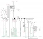
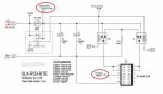
could you advice how is done functionally this connection, redline marked on the attachment?
How is current sense working with R7 resistance and how is R7 connected in circuit?
How is pin 6 of J5 socket connected to R9/R12 resistance and how is working with TH Sense? (meaning of TH Sense?)
Does has both of this same functionally for current validation vs sensing? Can PCB set current limitation or is not possible without IGBTs components...
Also wondering what is the power of transformer to handle chlorination cell T3, around < 500VA if there will be current less as 8 Amps.
Does anyone has axis chart how current amps relates to salinity ppm vs water temperature, curve Amps vs ppm vs Celsius?
Thanks for details.
Lukas from Finland
") In my pool i want to use Loxone system.
In my pool i want to use Loxone system.