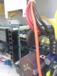
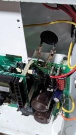
Hayward Aqua-rite Salt Water Chlorine Generator Thermistor Fix?

Jul 2, 2012
49
Central MS
After thinking about the issues I've had with the thermistor on my Hayward SWG and researching on the forum and google...I came across a mention about an external thermistor.

Hmmmm.... So that got me thinking.

What if you could solder a couple of leads from the pin where each leg of the thermistor solders into? On the other end of each lead - just have a receptacle that each leg of the thermistor could plug into? Essentially just making a pigtail or extension - and then just run it to the side of the main board. That way if you need to replace, or even just test the thermistor, you'd only have to take off the two screws to the main panel. It'd be as easy as changing out a fuse.

I'm definitely not an electrical engineer, so I have no clue on the specs or what gauge the leads should be - but for anyone familiar with all that jazz, could it be done without blowing up my house??
 
I'm in the process of helping my stepson diagnose a problem with his Hayward Aquarite Goldline, and I'm 99% sure it's the thermistor. I'm going over there later today to open the control unit up and see if I see any visible damage to that component. I've already got new thermistors, just in case - I bought a two-pack on Amazon for less than $6.

I thought about something exactly like what you propose, since my research online seems to indicate that these things can be a recurring problem with the Hayward controllers. I'll be interested to see what others say about this option.
 
If it’s not working right and you’re confident in your soldering skills, I’d go ahead and replace the thermistor just in case since you’ve already accessed the board. The first time my unit blew the factory one, there was a very noticeable separation. Every other time (about 3-4 since then) they “looked” fine but weren’t...only knowing they weren’t when I’d replace it and the unit would work again. The one I replaced this weekend did have a very minuscule raise. Hardly noticeable though. But since you’ve already got them in hand and they’re cheap...you don’t have much to lose!
 
I'm in the process of helping my stepson diagnose a problem with his Hayward Aquarite Goldline, and I'm 99% sure it's the thermistor. I'm going over there later today to open the control unit up and see if I see any visible damage to that component. I've already got new thermistors, just in case - I bought a two-pack on Amazon for less than $6.

I thought about something exactly like what you propose, since my research online seems to indicate that these things can be a recurring problem with the Hayward controllers. I'll be interested to see what others say about this option.
Could you take a picture and a link of the new thermistors for future use by me. Thanks
 
  • Like
Reactions: Chuckiechan
Could you take a picture and a link of the new thermistors for future use by me. Thanks
You bet. Link is below. FWIW I took a look at it today and the original thermistor was split right down the middle, sure enough. I soldered one of the new ones in, reconnected everything, and fired her up. Power light comes on... Generating light comes on... everything works! Hallelujah.

Here's the ones I bought: Ametherm SL32 2R025 (Pack of 2) Aqua-Rite Thermistor, ICL 2 OHM 20% 25A 30MM: Amazon.com: Industrial & Scientific
 
  • Like
Reactions: Thom53us
The Prologic circuit board does not use a thermistor. So, it seems like it can be eliminated.

I'm not sure why the Aquarite uses one whereas the Prologic doesn't.

Maybe the Prologic uses a different component to do the same thing.

It would be nice if they could eliminate it or make it plug in for easy replacement.
 
Usually you can see cracks in the coating on the thermistor indicating it’s bad. But like I said above, I’ve had a few that looked normal and couldn’t find any cracks - but they were bad. I never bothered with testing them because in order to access the thermistor...everything else is removed, it wouldn’t take me much longer to just replace it.

I don’t have pics, but I’m sure there’s a video somewhere which can be more helpful. But my understanding is that the thermistor on the SWG is a Negative Temp Coefficient (NTC) thermistor, so resistance will decrease as temp increases. The rating for the thermistor is 2 ohms at room temp (low 70’s F), which is about the reading you should get on a multimeter, give or take a little depending on temp. If it’s wayyy off, it’s bad. If it’s close, proceed. The next test is, while holding the two leads of the multimeter on the legs of the thermistor, apply a heat source (hair dryer, heat gun, etc.) for a few moments. The resistance reading should begin to drop as the heat source is applied. If not, it’s bad.
 

Enjoying this content?

Support TFP with a donation.

Give Support
Saw the pic on the left posted here somewhere. So I kindly asked a more knowledgeable friend to do the same to my r1.55 pcb. He told me that the newest pcb with firmware r1.59 had indeed, addressed the dreaded thermistor failure.
He decided to upgrade the firmware to r1.59 and soldered a relay to my old board as shown on the right to replicate the newer aqr pcb. My swg has been working fine since.
 
Oh wow - total McGuyver move with the binder clip...and I'm over here worried about burning down my house!

And yep - I checked my version. 1.58...blah. I'm gonna try a few things from the relay angle. I have a guy looking into it - but he's asking for a schematic of the main PCB. I've searched, but the only thing I've found is that a schematic of the main board for the SWG is like finding and striking oil. Lots of leads and almosts - but has turned up zilch so far. It'd be great if anyone posted one here. I did manage to find a few sub-sectional schems in this forum - hoping they'll help.
 
Replying to the original post about a way to change the thermister more easily, this is exactly what I did. Instead of unsoldering the thermister from the board, I simply clipped it off leaving the leads behind and soldered on some alligator clips on. When the new thermister arrived, I just clipped it in and turned the power back on. The best news was that when the replacement thermister blew again after 5 more years, it took about a minute to alligator clip in the replacement:
PXL_20230620_024527703.jpg
 
  • Like
  • Love
Reactions: alee63 and wireform
Interesting, may need to do this next time.

The thermistor fix saved me a lot of money this spring. :)
 
As a quick question, is the solder for these leaded? I didn't see a pb-free silkscreen anywhere on the actual PCB, but maybe I missed it.
Gotta know so I don't end up cross contaminating a pb-free station.
 

Enjoying this content?

Support TFP with a donation.

Give Support
Thread Status
Hello , This thread has been inactive for over 60 days. New postings here are unlikely to be seen or responded to by other members. For better visibility, consider Starting A New Thread.