Controlling Rs485 slave devices (heater, pump, SWG) directly with Pi

Thanks for the suggestion! Unfortunately, I see no real difference (other than the number of bytes per "packet"). I conducted an experiment trying each of SEVENBITS or EIGHTBITS, at each of 4800, 9600, 19200, 38400 baudrates. There wasn't a clear winner 🤦‍♂️

The results:
Code:
pi@raspberrypi:~/Downloads $ ./jandy_heater_control.py 
Opening rs485 serial connect on port /dev/ttyUSB0
 -> Serial port opened: RS485<id=0xb5a59710, open=True>(port='/dev/ttyUSB0', baudrate=4800, bytesize=7, parity='N', stopbits=1, timeout=1, xonxoff=False, rtscts=True, dsrdtr=False)
Read the next packet. It was 426 bytes, with dest 0x1
Read the next packet. It was 455 bytes, with dest 0x0
Read the next packet. It was 462 bytes, with dest 0x4
Read the next packet. It was 461 bytes, with dest 0x0
^C
KeyboardInterrupt

pi@raspberrypi:~/Downloads $ ./jandy_heater_control.py 
Opening rs485 serial connect on port /dev/ttyUSB0
 -> Serial port opened: RS485<id=0xb5a53710, open=True>(port='/dev/ttyUSB0', baudrate=4800, bytesize=8, parity='N', stopbits=1, timeout=1, xonxoff=False, rtscts=True, dsrdtr=False)
Read the next packet. It was 280 bytes, with dest 0xbc
Read the next packet. It was 419 bytes, with dest 0x1
Read the next packet. It was 415 bytes, with dest 0x1
Read the next packet. It was 430 bytes, with dest 0x14
Read the next packet. It was 447 bytes, with dest 0x0
^C
KeyboardInterrupt

pi@raspberrypi:~/Downloads $ ./jandy_heater_control.py 
Opening rs485 serial connect on port /dev/ttyUSB0
 -> Serial port opened: RS485<id=0xb5a96750, open=True>(port='/dev/ttyUSB0', baudrate=9600, bytesize=7, parity='N', stopbits=1, timeout=1, xonxoff=False, rtscts=True, dsrdtr=False)
Read the next packet. It was 744 bytes, with dest 0x0
Read the next packet. It was 744 bytes, with dest 0x49
Read the next packet. It was 460 bytes, with dest 0x0
Read the next packet. It was 753 bytes, with dest 0x60
Read the next packet. It was 765 bytes, with dest 0x1
Read the next packet. It was 753 bytes, with dest 0x8
^C
KeyboardInterrupt

pi@raspberrypi:~/Downloads $ ./jandy_heater_control.py 
Opening rs485 serial connect on port /dev/ttyUSB0
 -> Serial port opened: RS485<id=0xb59c6730, open=True>(port='/dev/ttyUSB0', baudrate=9600, bytesize=8, parity='N', stopbits=1, timeout=1, xonxoff=False, rtscts=True, dsrdtr=False)
Read the next packet. It was 704 bytes, with dest 0x0
Read the next packet. It was 694 bytes, with dest 0xc0
Read the next packet. It was 335 bytes, with dest 0x48
Read the next packet. It was 695 bytes, with dest 0x0
Read the next packet. It was 697 bytes, with dest 0x0
^C
KeyboardInterrupt

pi@raspberrypi:~/Downloads $ ./jandy_heater_control.py 
Opening rs485 serial connect on port /dev/ttyUSB0
 -> Serial port opened: RS485<id=0xb59cf730, open=True>(port='/dev/ttyUSB0', baudrate=19200, bytesize=7, parity='N', stopbits=1, timeout=1, xonxoff=False, rtscts=True, dsrdtr=False)
Read the next packet. It was 1407 bytes, with dest 0x50
Read the next packet. It was 1422 bytes, with dest 0x12
Read the next packet. It was 1386 bytes, with dest 0x50
Read the next packet. It was 1401 bytes, with dest 0x0
Read the next packet. It was 1401 bytes, with dest 0x50
^C
KeyboardInterrupt

pi@raspberrypi:~/Downloads $ ./jandy_heater_control.py 
Opening rs485 serial connect on port /dev/ttyUSB0
 -> Serial port opened: RS485<id=0xb5a0a790, open=True>(port='/dev/ttyUSB0', baudrate=19200, bytesize=8, parity='N', stopbits=1, timeout=1, xonxoff=False, rtscts=True, dsrdtr=False)
Read the next packet. It was 1303 bytes, with dest 0x88
Read the next packet. It was 1314 bytes, with dest 0x4
Read the next packet. It was 1278 bytes, with dest 0x2
Read the next packet. It was 1288 bytes, with dest 0x1a
Read the next packet. It was 1286 bytes, with dest 0x81
^C
KeyboardInterrupt

pi@raspberrypi:~/Downloads $ ./jandy_heater_control.py 
Opening rs485 serial connect on port /dev/ttyUSB0
 -> Serial port opened: RS485<id=0xb5a17650, open=True>(port='/dev/ttyUSB0', baudrate=38400, bytesize=7, parity='N', stopbits=1, timeout=1, xonxoff=False, rtscts=True, dsrdtr=False)
Read the next packet. It was 2400 bytes, with dest 0x0
Read the next packet. It was 2367 bytes, with dest 0x0
Read the next packet. It was 1803 bytes, with dest 0x0
Read the next packet. It was 2397 bytes, with dest 0x30
^C
KeyboardInterrupt

pi@raspberrypi:~/Downloads $ ./jandy_heater_control.py 
Opening rs485 serial connect on port /dev/ttyUSB0
 -> Serial port opened: RS485<id=0xb5a2c770, open=True>(port='/dev/ttyUSB0', baudrate=38400, bytesize=8, parity='N', stopbits=1, timeout=1, xonxoff=False, rtscts=True, dsrdtr=False)
Read the next packet. It was 2242 bytes, with dest 0x5
Read the next packet. It was 1988 bytes, with dest 0x14
Read the next packet. It was 2200 bytes, with dest 0x0
Read the next packet. It was 2194 bytes, with dest 0x10
Read the next packet. It was 2218 bytes, with dest 0xd5
Read the next packet. It was 2237 bytes, with dest 0x35
^C
KeyboardInterrupt

Looking here, I think 9600, EIGHTBITS, STOPBITS_ONE are the right settings:
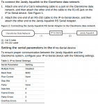
Screenshot from 2021-01-25 17-26-13.png
... but this does mention RS-232 instead of RS-485. But I don't think that matters? RS-485 is just like the more industrial, noise resistant transport? Either way you are reading some number of bits by looking at voltages on pins at some interval, right?

I guess next step is to check the wires again. Maybe if I invert Data+ and Data- something will work? I thought I tried that before and got nothing. But, not sure what else to do. Wish I was better at this stuff!
 
I have a Hayward heater for my spa, and a Hayward vsp for my pool
I control both with relays. The heater has a 2 wire and 3 wire remote control mode. I use the 3 wire mode. Two relays. You short the common wire to one input to go into pool mode, and the other input to go into spa mode. Only difference is the temp setting. Set the temp manually, then you can close the relay and start the heater.

With the VSP, there are 4 wires, common and 3 inputs. The three inputs support selecting 7 speeds, each combination is a different speed. All zeros is off. So takes three relays to control.
You can select the speeds you want in the setup menu.
Here is info for the pump
My Pump control info
I didn't take pictures for the heater wiring, but it was pretty straightforward.

You just need small, signal relays to do this with.

This guy has info for the 485 interface to a hayward pump
 
The heater has a 2 wire and 3 wire remote control mode. I use the 3 wire mode. Two relays. You short the common wire to one input to go into pool mode, and the other input to go into spa mode. Only difference is the temp setting. Set the temp manually, then you can close the relay and start the heater.
This is a great idea, thanks! One of my goals here was to be able to control the temperature remotely, so that I can keep the (indoor) pool temperature colder most of the time when we're not going to be swimming in it but have a way to tell the system that we'll be swimming in a few hours so bring the temperature up. But this approach might work for be because I could just use the fact that the heater has two modes (pool/spa) and set them to two different temperatures (say, pool mode is "cold" and spa mode is "warm") and toggle between the modes.

I'll look into this, thanks!

As far as switching Data+ and Data-, that was a total bust. I got nothing, just as before. I'm now wondering if the issue has something to do with the fact that the VCC line doesn't work? Or maybe the missing termination wires that have no place to mount up? So weird...
 
Okay, so looking at the bytes being returned again, it really does look like random noise, maybe with some underlying oscillation (maybe why we get semi-regular packet sizes).

For documentation purposes, my next plan of attack is:
  • Get out the voltmeter and see what the Jandy voltage is VCC to ground. Maybe it is somehow not working with my RS-485 adapter? I really wish I could figure out if the jandy is properly terminated (or even understand what that means -- as a programmer, my electrical understanding is scant) or how to properly terminate it if it isn't. My hope was that this would "just work" because I bought a "good" RS-485 adapter, but maybe not?
  • Do packets stop coming if I turn off or unplug the heater? I'd hope so! Does it change the traffic at all?
  • Is there a three-wire control method as described above? How does it work?
  • Take photos with my phone in various lighting conditions and see if I can read the display programmatically with pyTesseract (could then control via on/off two-wire switch)
And, finally for now, how do you guys (@Katodude, @randytsuch) measure the temperature of the pool? This was one of the things I was hoping to get by interfacing to the jandy directly, as it clearly has a temperature sensor.

I use a DS18b20 temp sensor, and install as described here

Its not hard, but you do need a tap to do it like I did. Tapping plastic pipe is easy though. I would recommend making the hole at a joint where its thicker, not in the middle like I did.

But, if I was starting now, I'd probably use a thermistor. Jandy and others sell them that are designed to mount in pool pipes. When I did it a few years ago, I couldn't figure out how to read a thermistor with an ESP. Now google turns up some hits and it looks fairly easy. I'm sure you can do it with a pi too.

For your 485 problems, a scope is really what you need to see what's going on. But I know that most people don't have access to scopes.

If it was 232, that would be a problem, but I looked at the Jandy heater manual, and it says its 485.
What model heater do you have? I was looking at a Jandy manual, but the figure looks different from your pic.
The manual I was looking said the control panel is 485 too. So you will see 485 traffic from the control panel interface. But I don't see the wires to the control panel in your pic.

Randy
 
idealist, do you have a multimeter? One possibility might be a lack of termination. If there was nothing connected to the RS485 bus before, it might be unterminated. Since the heater is intended to connect to an RS panel, and the panel has a terminating resistor already, the heater quite reasonable may not be terminated at all. Measure resistance across the + and -, and if you don't have something in the same zip code of 60 to 120 ohms you might want to find some resistors. Check your USB adapter, it may offer the option too with a jumper or something. If the bus is unterminated, the signal lines will float and your logic (voltage) levels will be basically uncontrolled. You'll get garbage data. The resistance isn't terribly critical, especially if your wire length is short. I'm only terminated on one side (by the RS panel) with run length of about 100 feet, and it gives me no problems. If you don't have a multimeter but can get your hands on a 120 ohm (or so) resistor, just stick it across the + and -.

You shouldn't worry about the VCC from the heater at all. Leave it disconnected. The USB adapter supplies power to the RS485 bus on its side, the heater on the other.

If you unplug the heater, the bus would go quiet (0V) unless you are sending data from your dongle.

Don't know if Jandy does three wire, but for the Hayward heater it's a super simple method of control. You have a common wire, a "pool" (low temp setting) wire and a "spa" (high temp setting) wire. Connect common to "pool" (like with a relay or even by touching the wires together) and the heater turns on, maintaining the "pool" temperature setting with its own internal thermostat. Likewise for the "spa" wire.
 

Enjoying this content?

Support TFP with a donation.

Give Support
Wow, thanks for all the great suggestions! I'm out for the next few days but will get back on this next week and report back.

idealist, do you have a multimeter? One possibility might be a lack of termination. If there was nothing connected to the RS485 bus before, it might be unterminated. Since the heater is intended to connect to an RS panel, and the panel has a terminating resistor already, the heater quite reasonable may not be terminated at all. Measure resistance across the + and -, and if you don't have something in the same zip code of 60 to 120 ohms you might want to find some resistors. Check your USB adapter, it may offer the option too with a jumper or something. If the bus is unterminated, the signal lines will float and your logic (voltage) levels will be basically uncontrolled. You'll get garbage data. The resistance isn't terribly critical, especially if your wire length is short. I'm only terminated on one side (by the RS panel) with run length of about 100 feet, and it gives me no problems. If you don't have a multimeter but can get your hands on a 120 ohm (or so) resistor, just stick it across the + and -.
Thanks for the detailed advise here, @superuser! I do have a multimeter and can test this! I don't know if my adapter is terminated, but can do the test you suggested. That would never have occurred to me to test -- why would there even be continuity between Data+ and Data-? But garbage data is definitely what I'm seeing. The wire length is not long, so I'm hopeful this will make a big difference.

Questions:
  1. Should I measure the RS-485 adapter's Data+/Data- wires or the heater header Data+/Data- terminals, or both?
  2. When I do the resistance measurement, should I have the RS-485 adapter plugged in to the computer or not? Should it be plugged into the heater?
  3. Do I just plug the resistor in across the Data+ and Data- terminals at the heater header along with the wires from the RS-485 adapter? Seems super janky, but maybe that's the right thing to do. I really need a decently "for idiots" electrical primer. Physics II was 20 years ago. (OMG I'm old). Probably need an oscilloscope, too.
I do have a little set of resistors, I'm hopeful there's a 60 or 100 or 120 ohm one in there.

You shouldn't worry about the VCC from the heater at all. Leave it disconnected. The USB adapter supplies power to the RS485 bus on its side, the heater on the other.
So, what if one side is applying 24V logical and the other is operating on 5V logical? That doesn't screw anything up? How does anything work?

If you unplug the heater, the bus would go quiet (0V) unless you are sending data from your dongle.
Yeah, right now my script is read-only, so this is what I'm hoping for, too.

Thanks again!
 
I use a DS18b20 temp sensor, and install as described here

Its not hard, but you do need a tap to do it like I did. Tapping plastic pipe is easy though. I would recommend making the hole at a joint where its thicker, not in the middle like I did.

But, if I was starting now, I'd probably use a thermistor. Jandy and others sell them that are designed to mount in pool pipes. When I did it a few years ago, I couldn't figure out how to read a thermistor with an ESP. Now google turns up some hits and it looks fairly easy. I'm sure you can do it with a pi too.
Thanks for this suggestion! That does look way easier than I thought it would be. I'm hopeful I can bend the RS-485 bus to my will, but this is a nice back up plan.
 
To answer your questions:
1. Doesn't really matter if they're connected, you can measure them as a system or individually. But you'll want to power both down your adapter and the heater to ensure they aren't driving (powering) the bus. You can disconnect and measure them individually to see if either are terminated though, but all that really matters in your setup is that the bus is indeed terminated. If it were me, I'd leave it all connected, turn off the heater, and measure the resistance between the data lines.
2. It won't matter if it's plugged into the PC, unless the adapter is trying to send data. As I mentioned above, you can leave it all connected if you like - just power down the heater to make sure it isn't transmitting.
3. You can stick the resistor across the Data +/- terminals at either end. Choose which end is more convenient and go with it. Or, if your adapter offers a jumper to do it, that would be easier. You can even terminate both ends of the bus and have it all still work, as long as the drivers have enough juice to overcome the resistance. Roughly 60 ohms is the accepted minimum.

For the VCC question, the point I wanted to make is that you don't want to connect VCC from the heater to anything. You also don't want to connect the VCC from your adapter to anything. Think of those as "convenience outlets" for whatever gear might be connected, but in your case both sides have their own power supplies. Your computer is powering the adapter, and the heater is powering itself.
 
Okay, so it's been two weeks since I've posted, but I haven't given up yet! However, I still haven't been victorious in getting the RS-485 connection to provide sensible data.

Based on the generous help and input from @superuser and others, I performed the following tests using my multimeter. The goals was to ensure resistance at the heater terminal heads measured between Data+ and Data- was ~100 Ohms. The tests are presented in a more logical manner than the order in which they were actually conducted, because I'm totally just trying stuff as it comes to me.

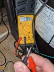
First, ensure multimeter is working as expected:

PXL_20210204_025035837.jpg
Result: Multimeter appears to be working as expected.

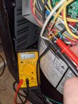
Second, test resistance at heater terminal headers:
PXL_20210204_025213780.jpg
Result: Uncertain: is there expected to be any continuity between Data+ and Data- even when unterminated? In any case, my multimeter picks up infinite resistance (no continuity) between Data+ and Data- at the heater terminal headers?

Third, test resistance of USB RS-485 adapter:
PXL_20210204_025054382.jpg
Result: Identical to heater terminal headers. There is no continuity between Data+ and Data-.

Fourth, attach 100 Ohm resistor between Data+ and Data- lines on the RS-485 USB adapter and reattach the wires to the heater terminal headers:
PXL_20210214_003721763.jpg
Result: Success? ~100 Ohm resistance detected between Data+ and Data- at heater terminal headers.

Unfortunately, after adding the 100 Ohm resistor, I get nothing from the heater. My script does not see any data arrive. I also tried with a 200 ohm resistor. I also tried plugging/unplugging the heater, hoping maybe it just sends some message on power up instead of at regular intervals. No dice. My script is set to readonly, 9600 baud, eight-bit bytes, no parity and one stopbit.

Anyone got anymore ideas? I haven't given up yet, but I am kind of out of ideas. Do I need to buy an oscilloscope? How good of one? Is it possible that the device is quiet on the RS-485 bus until it sees some kind of broadcast message from the panel and only then starts broadcasting?

As far as the backup suggestion goes, I did test out the 3-wire remote and it works perfectly! So that is a nice backup, but it would require a digital temperature sensor to be put in line somewhere and is still slightly less preferable to me than reverse engineering this RS-485 bus.

As always, thanks everyone for any and all suggestions!!
 
I realize I posted the above at a potentially particularly inopportune time for a number of users here. I hope you and your families (and your pools!) are all okay!

l hope it's okay to give this thread a "bump" in the hopes that there's someone out there with some ideas, because I am out of them....
 
It does sound like might indeed be sitting there listening. While a scope would definitely make it very clear, there's more you can do with your meter. If you measure AC volts across Data + and Data -, you should see something non-zero, maybe up to 1.5V if it's transmitting. If you see zero, it's not driving the bus and sitting there listening. RS485 is a half-duplex tech, so only one device can transmit at any given moment. The heater might be waiting for a request to show up on the bus from an RS controller before it'll respond. Sorry, wish I knew more about what to expect.
 
Thread Status
Hello , This thread has been inactive for over 60 days. New postings here are unlikely to be seen or responded to by other members. For better visibility, consider Starting A New Thread.