Are there any Electrical Engineers on here?

Nov 18, 2017
42
Atlanta, GA
I am working on decoding the signals sent from my Sundance 850 control panel J7 to the topside controls. I believe that if I can decode these signals, I can create a non-obtrusive wifi remote control without degrading the built in protections for the tub. This is a personal venture to add remote temperature adjustment and put the pumps on my own schedule. The plan is to build in a raspberry pi with a python program to run the button pushes remotely. There is almost zero info on these circuits online. The only thing that comes close is THIS.

What I have:

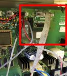
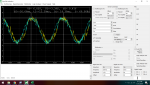
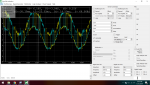
I have oscilloscope readings of the 10 pins that make up the J7 jumper on the 850. I can tell what they are (hz, voltage, wave form), but not necessarily how to interpret them. I am planning on getting some more readings to see if I can identify all the different button presses. I can get printouts of all the clock timings and wave types, along with the button presses in action.

I am hopeful that I can mimic with a signal generator the button pushes, as though I was standing at the tub. I don't care as much about knowing the current state of the pumps, but the state is visible on the topside panel so it should be theoretically possible..

I also want to read off the temp. I believe I made progress on this front. The logic analyzer picked up a signal on one of the leads of
0x60 which equals 96 in decimal. This was equal to the current temp, but I can't confirm that that was what the reading was, because I got some other random numbers too. Until I can interpret the signals, I don't think I can extract usable data for a program.

If anyone is feeling adventurous, can help reverse engineer a Sundance board, or has some engineering schematics for the 850 lying around any help would be greatly appreciated.
 
  • Like
Reactions: manfacro
I am a EE, and work as a test engineer doing software. It looks like your spa is about 20 years old or so. So it might be difficult to find that sort of information.

I have a new Maax (American Whirlpool) that uses Balboa controls and the head unit to the controller is known to speak RS-422. There is open source code for it.
You could always spend five hundred bucks on a new controller with known protocols or even with a wifi module. So the project is doable but it might be too much work if you are looking at an unknown module. But you have options regardless up to replacing the control modules with something more modern.
 
  • Like
Reactions: smithlevenson
OK, it appears that Sundance uses Balboa controls.

Look at this and see if the received data makes sense to you. One comment says it's RS-458... I think they mean 485 which is a superset of 422...


Search on Sundance Balboa and on Balboa protocol. Hopefully the older controllers use the same or similar commands and protocol. Good luck.. It could be a really fun project.
 
  • Like
Reactions: smithlevenson
OK, it appears that Sundance uses Balboa controls.
Look at this and see if the received data makes sense to you. One comment says it's RS-458... I think they mean 485 which is a superset of 422...
The protocol is RS-485 and the link Fred provided should work for most of the commands.

The waveform definitely looks like RS-485. I will need to see if I can get my logic analyzer to read RS-485. That would simplify things greatly. I will read up on the standard, so I can compare to the signal.

Part of the message may be something else since it has a much larger Voltage deferential than 12 volts. I will get some snapshots of the readings tonight. I will also get the chip information, which should shed some light on the proper timings.

Thanks for taking the time to point me in the right direction!
 

Attachments

  • Control Panel Connection.jpg
    Control Panel Connection.jpg
    562 KB · Views: 17
I took some readings today with my oscilloscope and while I don't think it is extremely accurate. It should be in the ball park.

Here are the basics:

The line from the board has a coupler for another 3 button panel with no display.

10 pins
Pin 1-2: 7.5V +/- 60hz (Could be +/- 1V to 2V according to the manufacturer)
Pin 3-5: 1.75V +/- 60hz
Pin 6-9: Same as 1-2
Pin 10: Shifted up 2.75V out of phase above pin 1-2 but still 7.5V +/-

Button Pushes:
Heater, Pump 1, 2 , Blower OFF: Same as above
Heater On | Pump 1, 2 , Blower OFF: Pin 1-2 are 500mv +/-
Pump 1 Button Press | Pump Heater, 2 , Blower OFF: Shifts 2.5V +/- out of phase
Pump 2 On | Pump 1, Heater , Blower OFF: 4.75V +/-
Blower On | Pump 1, 2 , Heater OFF: 4.85V +/- ( This was tough to measure, but was definitely a change)

I don't really know what to make of it all but I will attach some screen shots of the oscilloscope if you guys can make heads or tales. One is with Pump 2 on, the other is the Pin 10 "shift"

The logic analyzer is still grabbing data, but it is hard to capture and save. It is also not exactly obvious what is going on when it is flashing numbers like crazy. I need to figure out some kind of baseline if I am going to pull any useful data off.
 

Attachments

  • 2019-07-31 (1).png
    2019-07-31 (1).png
    110.7 KB · Views: 14
  • 2019-07-31.png
    2019-07-31.png
    129.2 KB · Views: 14
You could be my life coach with that kind of advice. I typically make a situation extremely complicated, break it, and then learn everything about it trying to fix it. Hopefully I can learn something useful long term out of analyzing these signals.
It's more fun that way.
 
  • Like
Reactions: smithlevenson
RS-485 is an electrical specification in the same manner as RS-232 is. Specifies voltage levels some timing etc. In particular RS-485/422 is two wire differential with a voltage swing between the two wires of at least +/-1.2 volts to +/-5 volts. This would appear to be on an oscilloscope a square wave. The protocol is how data is sent over the wire. In general serial data is comprised of groups of 6 to 8 bits with at least one to two bits spaces between groups.Standard is one start bit, 7 or 8 data bits sometimes a parity bit and then a stop space.

A good resource for serial data info:
 

Enjoying this content?

Support TFP with a donation.

Give Support
RS-485 is an electrical specification in the same manner as RS-232 is. Specifies voltage levels some timing etc. In particular RS-485/422 is two wire differential with a voltage swing between the two wires of at least +/-1.2 volts to +/-5 volts. This would appear to be on an oscilloscope a square wave. The protocol is how data is sent over the wire. In general serial data is comprised of groups of 6 to 8 bits with at least one to two bits spaces between groups.Standard is one start bit, 7 or 8 data bits sometimes a parity bit and then a stop space.

A good resource for serial data info:

Thanks. The logic analyzer was picking up some square waves and was reading the data. It looked garbled, but having read how other hot tubs read out data, it may not be as garbled as I first thought. I just need a way to capture it reliably. I will see if I can narrow it down this afternoon. The only concerning part is how many people have tried and given up on communicating over the serial port on various hot tubs.
 
You can buy actual RS-422/485 adapters (like ones directly to USB) instead of the typical RS-232 ones pretty readily. Just verify that the specs are as the post above is. A lot of people give up because it is non trivial. I might be a little concerned as your module is identified as being about 20 years old on the internet and it's possible that the serial interface didn't happen on Balboa controls until later. 422/485 is a true differential interface unlike RS-232 so your protocol analyzer needs to be on the proper pins with the proper polarity and also set for the proper mode to decode the data. And yes, it's a short binary format,s o that is why I suggested looking at the library since it's pretty completely reverse engineered there... assuming it is the same as your controller... good luck....
 
  • Like
Reactions: smithlevenson
As a EE myself with a few years into retirement, I always have to ask myself when confronted with questions like you're pondering: "How much is your time worth?". I, also, am a bit stubborn (ask my wife) and I completely get the challenge/learning new stuff aspect of the task you've set out upon, but I'd lean towards an new controller. Just sayin'.
Half of the battle is finding the time. I have a good start, and the coding part should be pretty easy. If it isn't easy to read and write consistently, then you will be 100% correct. It just seems like with the simplicity of the button pushes, the ability to simulate button pushes should at least be obtainable. I can hack temp read outs from a cheap hardware standpoint pretty easily.

Plus someone on the internet needs to finish this so people can Google it and be like "heck no, I'm not doing that"
 
@Rattus Suffocatus @tucsontico @dschlic1

I got the logic analyzer hooked up and pulled data off of two pins at a time, so only the neighboring pins are in sequence. I don't know what the timing was between data Tx. This is where I am a little out of my depth. I have never written any code or programmed a logic chip to send and receive data over serial in Hex. I put it in an excel spreadsheet and it may not tell the whole story. At the time only pump 1 was running. All of it is converted from hex to decimal. I have no idea if that was the right thing to do. If you wouldn't mind taking a look and seeing if you can steer me in any kind of direction. I can save in another format if you guys don't have excel.

Thanks in advance.

Link To Excel File
 
Like RS-232, RS-485 is asynchronous. There is no separate clocks, just start and stop bits. Typically 10 bits total for an 8 bit word. If you have determined that the signal is differential and RS-422 like, get a port adapter and hook it up to the line... Start monitoring it with a computer...
 
There are some guys doing this kind of work over at the nodejs-poolcontroller page. You may be able to link up with them. They have a chat page here. Useful links on how to capture RS-485 protocols here. And may just give you the help you need to get this figured out.
 
There are some guys doing this kind of work over at the nodejs-poolcontroller page. You may be able to link up with them. They have a chat page here. Useful links on how to capture RS-485 protocols here. And may just give you the help you need to get this figured out.
I am going to see if they have worked through what I am stuck on. I ordered their rs485 capture device. I will see if I can get more data.
 
  • Like
Reactions: cmc0619
So Good news on the controlling the pumps. The secondary set of switches on the topside for the pumps are just momentary shorts on the 5v line. So I can get the raspberry pi in place this weekend and control the pump schedule. I wanted to be able to run all the pumps on high at least once a day to really filter and circulate the water. I still will need data to read in to make them smart switches, but it was a small easy win for the project. I will get a example that will show he pinout as I know it today and add to it as I figure the rest out.
 

Enjoying this content?

Support TFP with a donation.

Give Support
Thread Status
Hello , This thread has been inactive for over 60 days. New postings here are unlikely to be seen or responded to by other members. For better visibility, consider Starting A New Thread.