And another Intellicenter Question

Plankton

Well-known member
Apr 13, 2008
94
Hi All!
Yes I know this has been beat to death, but I do have some questions before I dive into purchasing a system. I have read the threads on Intelliflo Automation by MyAZPool, and the reveiws also. I j=have just about read everything I could get my hands on also. Yes to me if is a little confusing. But here is what I want. An automation system that myself and my wife can control pretty easy, Set the pool heat or the spa heat and have the valves move accordingly ( which we have now) also turn on the spa blower wireless if possible. As far as my valves I have a intake and return valve, (automated) but I also have 3 other valves that I would like to automate to close or open to direct most of the flow to my Polaris 360 in the morning then open to the pool after about an hour. This way the Polaris can do it's thing and I can keep the pump running at around 2700 RPM then drop it down to 1800 for the remainder of the day. I would also like to control the water feature which is a separate pump Since I am going all out I might as well go for the salt system too. Right now I am looking at the:
52190
IntelliCenter System Load Center i8PS, IC40, Common Load Center (w/ Salt) -- Model Code: 5PSIC40 (includes 2 IntelliValves).
Reading and reviewing the posts on here, I am a little confused on what is standard and what the aux circuits are. So I have Master Temp 400 Heater, Intelliflo Filter Pump, Waterfall Pump, Spa Blower and 4 valves, plus the Intellichlor and two lights ( 1 Ea Pool/Spa). So I assume the Heater Filter Pump is one circuit, and everything else with the exception of the valves is on it's own circuit? Am I correct on this? That would make six circuits which would leave me two extra? Thanks for any and all help with this. As those of you who have purchased one this is a huge investment, I just want to make sure I understand what it is I am purchasing so I can make an informed decision. If I left out any information or if you have questions fire away please. Thanks in advance.
 
Are your lights 12v or 120v?
Do you want to control them separately ?
Heater bypass? Do you want to automate it?
Heater and swg -filter relay 1
Waterfall pump - relay 2
Spa blower - relay 3
Pool light- relay 4
Spa light - relay 5

By default you can control 4 valve actuators on the intellicenter, to do more you will need the ~200 valve expansion module
 
Thanks Ahutlin,
Pool & Spa Lights are 12V _ would like to control them separately as I do now.
Heater Bypass- I do not have one yet- But when I do put one in yes I would like to automate the control for this.
I see you have me at 5 relays, is the Intellichlor on a relay also? If not then I could drop down to the i5PS which would save me some money. Thanks in advance.
Intellichlor is on the filter relay with the heater. The price difference between the i5ps and the i8ps is not very big but should you ever want more relays the upgrade is spendy so I would go with the i8ps ( I went with the i10ps even though initially I only had 5 relays needed...I now only have 1 left)
 
How old is your heater? New MT have an actuator terminal and its controlled by the PCb on the heater itself.
I do not beleive this works for anyone as of yet ( though with the release of 2.017 there is rumor that with a firmware 1.1+ connected heater it will work)
 
Hi Guys,
Thanks for the Info! Bradgray my MT400 is about 3 years old, the manufacture date is 2016, but I bought it 3 years ago. Ahultin, Thanks I'll stay with the iP8 then just for future expansion if need be. As far as the valve actuators, what I would like to do is have them automated so when I am running the pump for the Polaris I can close off the floor and wall outlets and direst all the pressure to the Polaris so it will clean the pool. Then I can figure out what the best RPM to run the Polaris. After an allotted amount of time I would like to have the Polaris valve go to off and the wall and floor outlets open up. One last question, I have 2 Jandy 2440 valve actuators, will these work with the Intellicenter? I don't see why not, but better to ask. Thanks again for all the assistance!
 
  • Like
Reactions: bradgray
I would like to do is have them automated so when I am running the pump for the Polaris I can close off the floor and wall outlets and direst all the pressure to the Polaris so it will clean the pool
Without the valve expansion board you can control 4 actuators, 2 of which are reserved for suction and return. So you can add one for your Polaris plus one more.
 
@Plankton
1. When it comes to IntelliCenter systems, the "bundles" will usually result is savings versus purchasing what you need "ala-carte".
2. Typically PolyTec Pools sport the best prices on the Internet and they offer free shipping and their delivery is quick.
3. An IntelliCenter i8PSIC40 is $3,689.95 and the IntelliCenter i5PSIC40 is $330.00 less.
4. Both systems come with an IntelliChlor IC-40 (that should be fine for your size pool) w/Controller Board , Air and Pool Temp Sensors and two IntelliValve actuators.
5. If it were me, I would try to spend the extra $330.00 for the i8PS but only you can decide that. You'll be amazed how many uses you can find for those extra relays. Many of us have. You'll need to purchase one more additional IntelliValve Actuator for your heater bypass valve. That will give you a total of three IntelliValves.
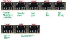
6. Here is a diagram of how you might connect up your devices to the high voltage relays.

1686708624088.png

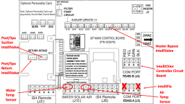
Based on what you have disclosed, you won't require a Valve Expansion Module. You still have one extra valve actuator connection left (Valve B) to do with what you will. Anymore than four valve actuators and YES, you will need a Valve Expansion Module.
Here is a diagram to sort of give you an idea of what connects to the Mother Card and Daughter Card.


1686709090474.png


BTW, having an extra relay or two isn't necessarily a bad thing. If one of the relays that are being used should fail (it happens), having a spare will get you back up and running right away.
r.
 
Last edited:

Enjoying this content?

Support TFP with a donation.

Give Support
Okay, I think I pretty much got it. But looking at the diagram, is the Intelliflow Com Port used in lieu of the Filter Pump relay or used in conjunction with it? Also I have been reading the Intellicenter Installation Manual, it's a long read, so I have an understanding on what I am up against. On the Daughter card what is the SPA plug in used for? I apologize for all the questions guys, but much appreciated for the help. If you could only see thr Rats Nest of wires I am dealing with now, I'm sure you would understand why all the questions.
I will need the daughter card though, I probably did not explain it clear enough (my mistake). Right now I have four valves, two Jandy automated and two manual. The automated ones control the Pool/Spa Intake and the Pool/Spa Return. Then there are two manual valves on a manifold, one controls the flow to the Polaris 360 and the next in-line one downstream controls the flow to the wall and floor outlets. So that would be four, and I plan on adding a bypass valve to the heater, just from everything I've read on here for good measure. So that would be a total of five, unless I am missing something.
I have looked at PolyTec Pools and yes they do have the lowest prices, so that is probably where I will purchase my system from. Once again, thanks to all for the time to explain and help.
 
the Intelliflow Com Port used in lieu of the Filter Pump relay or used in conjunction with it
Intelliflow pump gets connected to the line side of the filter pump relay so it is constantly powered, it is then controlled by the rs485 connection. The load side of the filter pump relay powers the heater and swg. This ensures that the heater and swg can only run whe the pump is running.
one downstream controls the flow to the wall and floor outlets
Is this one mostly a set it and forget it? The valve actuators ( even the intellivalves ) currently only have a start and stop position so its not like the valve actuator will give infinite adjustability. If so then yiu save ~200 on the valve expansion board.
 
  • Like
Reactions: MyAZPool
Okay, I think I pretty much got it. But looking at the diagram, is the Intelliflow Com Port used in lieu of the Filter Pump relay or used in conjunction with it?
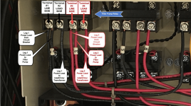
The Filter Pump Relay is where the IntelliFlo Pump obtains it's power. Like @Ahultin said, the IntelliFlo Pump power leads (L1 and L2), are connected to the LINE Side Terminal Screws of the Relay (T1 and T3). These are the same two terminal screws where the power leads from the circuit breaker connect. - i.e. The pump will be connected to power all of the time. It's the IntelliCenter that commands the pump to actually "run". This is accomplished through the control cable connected from the pump to the COM port. The heater and the IntelliChlor power leads are connected to the LOAD Side Terminal Screws of the Relay (T2 and T4).
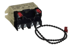
Power Relay (P/N 520106) Filter Pump (FLTR) / Auxiliary (Aux) Line-Voltage (power) Relay:​
1686751113094.png

The purpose of the IntelliCenter power relays are to control the On/Off features of line-voltage pool equipment such as pumps (see NOTE below), lights, low-voltage lighting transformers, blowers, etc. The relays are mounted on the upper power relay mounting platform at the top of the high-voltage compartment within the IntelliCenter Load/Power Center.
According to some references, the Pentair Power Relays support a maximum of 20 amps. But the relay itself indicates a maximum of 25 amps. It may be possible that Pentair de-rated the amperage of the power relay. I cannot say with any confidence.​
Five (5) power relays are included with the Load Center. Additional relays are included with the i8P / i8PS (3 additional) or i10P / i10PS (5 additional) Personality Kits. Further information on kits can be found in Section 8. of this guide.​
These relays are identified and controlled within the various IntelliCenter user interfaces as Filter Pump (FLTR) and Auxiliary (AUX) Circuits.​
The relays feature a low voltage control wire that plugs into the associated 2-pin connectors identified as Filter Pump (FLTR) and auxiliary (AUX1, 2 etc.) circuit connectors on the motherboard as illustrated or certain daughter cards (as applicable).​
There are four (4) terminal compression screws on the forward bottom of the relay, each of which allows two leads to be connected.​
The 1st and the 3rd (left-to-right) compression screws (LINE SIDE) are designated to be wired to the associated circuit breaker and consequently remain continuously energized (HOT), unless the applicable circuit breaker is “flipped” off manually or tripped for some reason.​
The 2nd and the 4th compression terminal screws (LOAD SIDE) are designated to be wired to the line-voltage item itself (pumps (see NOTE below), lights, blower, etc.) The LOAD SIDE terminals are only energized when the circuit has been turned on through the automation system either manually or through a scheduled event.​
The power relay is designed to control either 240 Vac or 110 Vac equipment and devices.​
If the relay is used to control a 240 Vac device - The 1st and 3rd compression terminal screws (LINE SIDE) are used to connect each leg of the 240 Vac circuit to the associated circuit breaker.​
The 2nd and 4th compression terminal screws (LOAD SIDE) are used to connect each leg of the 240Vac circuit to the applicable line-voltage device (pump (see NOTE below), blower, etc.)​
If the relay is used to control a 120 Vac device - Then the 1st compression terminal screw is used to connect the 120 Vac circuit (“black” power leg) to the applicable single-pole breaker.​
The 2nd compression terminal screw is used to connect the 120 Vac circuit (“black” power leg) to the applicable line-voltage device (light, low voltage lighting transformer, etc.). The “white” neutral leg is connected to the neutral bus bar or in the case of GFCI circuit breakers, to the terminal screw located on the breaker for that purpose and the white pigtail from the breaker connects to the neutral bus bar.​
NOTE: When connecting any Pentair IntelliFlo pump (VS, VF, VSF), the power connections to the IntelliFlo pump DO NOT adhere to the above example.
1686751168120.png
Pentair IntelliFlo pump power leads MUST BE connected to continuous power in order to function properly and as designed.
One method is to connect the IntelliFlo power leads to the LINE SIDE (1st and 3rd compression terminal screws) of the power relay.​
The other method would be to simply connect the IntelliFlo power leads directly to the applicable circuit breaker.​
Both connectivity options allow the IntelliFlo pump electronic circuits to receive power continuously, unless of course the circuit breaker is flipped off manually or tripped for some reason.​
The IntelliFlo pump motor is turned On/Off through the automation system circuitry, via the IntelliFlo RS-485 Control Cable which is connected between the pump and the RS-485 connectors on the IntelliCenter motherboard (J4 or J5).​
Connecting an IntelliFlo Filter Pump to the LOAD SIDE terminals of the Filter Pump Relay is NOT correct and seems to be a common mistake made by installers who are not familiar with the IntelliFlo line of pumps and/or Pentair Automation Systems.​

@Plankton
The two leads from the IntelliFlo Control Cable then connect to the "RS-485 COM PORT (J4)".
Simply put, the IntelliFlo power is connected to the LINE Side of the Relay. The IntelliFlo Control Cable is connected to the COM Port.

Okay, I think I pretty much got it. But looking at the diagram, is the Intelliflow Com Port used in lieu of the Filter Pump relay or used in conjunction with it? Also I have been reading the Intellicenter Installation Manual, it's a long read, so I have an understanding on what I am up against.
Yep, Pentair documentation is difficult to understand. Their Technical Writing requirements surely went to the "lowest bidder"..

On the Daughter card what is the SPA plug in used for?
The "SPA" connector on the daughter card is not applicable to your setup.

I apologize for all the questions guys, but much appreciated for the help. If you could only see thr Rats Nest of wires I am dealing with now, I'm sure you would understand why all the questions.
No need to apologize. That's what this forum is all about. We all have questions and concerns from time-to-time and it's nice to be able to find help from others who might have the answers or suggestions... :goodjob:

I will need the daughter card though, I probably did not explain it clear enough (my mistake).
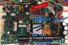
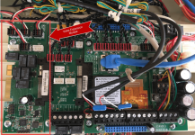
The daughter card will come "bundled" with any of the PS kits. That is the card just to the left of the mother card labeled "Optional Personality Card", in the diagram above. No need to purchase it separately.

IntelliCenter Daughter Card (Personality Card): An IntelliCenter Daughter Card is an additional circuit card that “slide-connects” to the left of the Motherboard. The daughter card defines the additional “personality” of the IntelliCenter System (if applicable) when any of the following exists:​
1686751055599.png
When more than five (5) line-voltage type power circuits are required (Filter Pump Circuit + 4 Auxiliary (AUX) Relay Circuits).​
- When there is more than one body of water, i.e. Pool and Spa.​
- When a Pool and Spa are present in the installation and each utilize their own separate filtration systems.​
The daughter card will include 3 or 5 additional auxiliary line-voltage type power circuits depending on the model and one additional iS4 remote connection (J2). SPA, INTAKE and RETURN valve actuator circuits are provided on “PS” models. The “D” model includes several duplicate circuits and is further detailed below in Section 8. below.​
There are six different daughter or “personality” cards available (i8P, i10P, i5PS, i8PS, i10PS, i10D), all of which can be purchased bundled within Personality “Kits” or the applicable daughter card can be purchased separately, if a user determines that more line-voltage type auxiliary relay circuits are required at a later time.​


Right now I have four valves, two Jandy automated and two manual. The automated ones control the Pool/Spa Intake and the Pool/Spa Return. Then there are two manual valves on a manifold, one controls the flow to the Polaris 360 and the next in-line one downstream controls the flow to the wall and floor outlets. So that would be four, and I plan on adding a bypass valve to the heater, just from everything I've read on here for good measure. So that would be a total of five, unless I am missing something.
Yes, you will require the "Valve Expansion Module" (P/N 522038Z), IF you are planning for five (5) valve actuators. You can find it here - Pentair IntelliCenter Valve Expansion Module
IntelliCenter Valve Expansion Module (P/N 522038Z): The purpose of the optional Valve Expansion Module is to allow for more than four (4) valve actuators (PS models) or more than two (2) valve actuators (P models), to be controlled by the IntelliCenter. It allows for a total of eight or ten valve actuators to be connected to the system respectively.​
You will only require this module if you plan on utilizing more than four (4) valve actuators for the “PS” models or two (2) valve actuators for the “P” models. See also: IntelliCenter Control System Personality and Expansion Card Installation Guide.​
1686750977110.png

@Plankton
Couple more things.
1. You may find the following link helpful as you explore the world of IntelliCenter.

2. If your planning on performing all of the electrical work yourself (converting your current setup to the IntelliCenter, etc), I just throw this out for consideration.
If you are not qualified and proficient in electrical installation practices and procedures, please consult with a licensed professional that IS qualified and proficient in swimming pool electrical installations.

Hope this helps...
r.
 
Last edited:
Okay, now I got it! I didn't realize the Intellicenter takes control of the pump settings! It does this through the RS485 connection Got it!
Now for the valves, currently they are set it and forget, but what I would like to do is have the floor/wall valve go full closed, while the Polaris valve goes full open. This way I can run the Polaris and and not have an extreme high flow going through the heater. My other idea would be if I install a bypass valve for the heater I could close off part of the flow and raise the pump RPMs up to run the Polaris. Right now with the low RPMs (2300) I have the pump set on my Polaris barley moves around the pool. I have to raise the pump RPMs up to 3K before it actually starts moving around. I just want to get to a point where the Polaris is cleaning but I'm not putting too much flow through the heater.
 
Okay, now I got it! I didn't realize the Intellicenter takes control of the pump settings! It does this through the RS485 connection Got it!
Roger.... :goodjob:

Now for the valves, currently they are set it and forget, but what I would like to do is have the floor/wall valve go full closed, while the Polaris valve goes full open. This way I can run the Polaris and and not have an extreme high flow going through the heater.
You will be able to have one valve open and another close at the same time through the use of Circuit Groups (macros).

NOTE: As @Ahultin referred to above I believe, keep in mind that currently, you can only set TWO (2) positions on the IntelliValves. Those positions don't necessarily have to be fully open or fully closed. Those valve positions can be partially open to any position that you set. But for now, you only get two positions.

My other idea would be if I install a bypass valve for the heater I could close off part of the flow and raise the pump RPMs up to run the Polaris. Right now with the low RPMs (2300) I have the pump set on my Polaris barley moves around the pool. I have to raise the pump RPMs up to 3K before it actually starts moving around. I just want to get to a point where the Polaris is cleaning but I'm not putting too much flow through the heater.
The heater bypass valve will normally be in the closed position (not allowing water flow to the heater) unless you are heating the pool or spa.
You can have all sorts of various programs (Circuit Groups) for various activities. (i.e. Spa use, kids pool parties, etc.). NOTE: But not more than 16. :p

By using Circuit Groups, you can open or shut valves, change pump speed settings, turn lights on/off, turn your heater on/off, turn other pumps on/off (waterfall pump), turn your Spa Blower on/off, etc. etc., all by the tap of one button at your computer or from your mobile device.
And, these Circuit Groups can be associated with various schedules as well.
r.
 
Last edited:
Ahultin & My AZPool,
Circuit Groups sounds good! Exactly what I would want to do! I also want to thank you both for taking the time to clear up a bunch of items for me. Now I do have an understanding of how this would work, Granted it is a basic one, but as long as I have the basics, I can work on it from there on up. Doesn't mean I won't be asking more queations when I get one, but this is a very good start.
 
Thread Status
Hello , This thread has been inactive for over 60 days. New postings here are unlikely to be seen or responded to by other members. For better visibility, consider Starting A New Thread.