
15 June 2024 This is like starting up a chemical plant!
- Thread starter setsailsoon
- Start date
You are using an out of date browser. It may not display this or other websites correctly.
You should upgrade or use an alternative browser.
You should upgrade or use an alternative browser.


You underestimate my desire to go home.GBOGH.
It's all I think about all day.

- Oct 25, 2015
- 5,432
- Pool Size
- 28000
- Surface
- Plaster
- Chlorine
- Salt Water Generator
- SWG Type
- CircuPool RJ-60 Plus
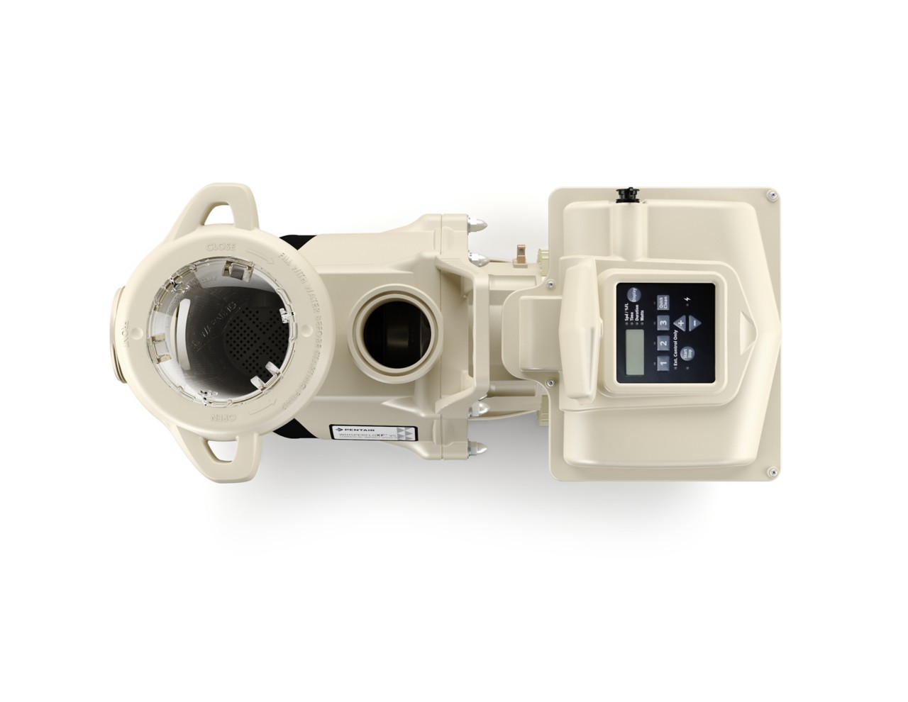
Wow! That's a monster pump. I think you mentioned this previously and somehow I forgot. Literature doesn't say the breaker size but 21 a max so 25 amp breaker? 2.5 or 3" suction plumbing would actually be easier and cheaper than plumbing for two pumps. Looks like Polytec normally carries it for $3000 so price is actually cheaper than two 3 hp pumps. Savings will help pay for the guts of my home-made RO system to get the tannins out of my crappy water. I'll get it through a professional installer so may pay a little more w warranty. This also makes other aspects of the project easier. Automation is very flexible with Pentair 485 interface and digital inputs. Min flow looks to be way lower than I'll need (extrapolating on the bottom of the pump curves for 300 rpm). Simpler equipment pad... what's not to like? SOLD!
Another great solution by @JamesW!
Thanks much Buddy!
Chris
Another great solution by @JamesW!
Thanks much Buddy!
Chris
I would do dual unblockable drains and have (2) 2" or (2) 2.5" lines from each unblockable drain to a 3" T and then each 3" line to a 4" T to go back to the pump.
Do not underestimate the value of getting the suction line sized correctly.
If you size it too small, it will never work correctly.
You should be able to run the pump at full speed without getting anywhere near cavitation.
This means that the suction head loss needs to be under 17 feet maximum.
Ideally, you would keep it below about 8 to 10 feet to be safe.
If the pump is above the pool, you have to count that as part of the head loss.
I would size the suction for 235 GPM even if you never plan to go that high.
- Jul 21, 2013
- 55,445
- Pool Size
- 35000
- Surface
- Plaster
- Chlorine
- Salt Water Generator
- SWG Type
- Pentair Intellichlor IC-60
Literature doesn't say the breaker size but 21 a max so 25 amp breaker?
Breaker has to be 80% of rated amperage.
If max amps are 21 then you need a 30 amp breaker with probably 10 gauge wire.
What about a 26.25 amp breaker?Breaker has to be 80% of rated amperage.
If max amps are 21 then you need a 30 amp breaker with probably 10 gauge wire.

Last edited:
- Oct 25, 2015
- 5,432
- Pool Size
- 28000
- Surface
- Plaster
- Chlorine
- Salt Water Generator
- SWG Type
- CircuPool RJ-60 Plus
- Oct 25, 2015
- 5,432
- Pool Size
- 28000
- Surface
- Plaster
- Chlorine
- Salt Water Generator
- SWG Type
- CircuPool RJ-60 Plus
Thanks, I'll go with the most conservative. The over-flow basin is where I will take suction most of the time and it's bottom is level with bottom of the pool. Normal operation is 12"- 24" off bottom inside the basin. Max pool depth is 7' plus floor concrete and plaster thickness. So with this and pipe bends I'll be close to 10' since pump pad is about 1' above pool surface. This seems like a great place to be conservative. Schedule 80 like the well suction lines?I would do dual unblockable drains and have (2) 2" or (2) 2.5" lines from each unblockable drain to a 3" T and then each 3" line to a 4" T to go back to the pump.
Do not underestimate the value of getting the suction line sized correctly.
If you size it too small, it will never work correctly.
You should be able to run the pump at full speed without getting anywhere near cavitation.
This means that the suction head loss needs to be under 17 feet maximum.
Ideally, you would keep it below about 8 to 10 feet to be safe.
If the pump is above the pool, you have to count that as part of the head loss.
I would size the suction for 235 GPM even if you never plan to go that high.
View attachment 514926
Chris
4" schedule 40 is pretty heavy duty, so I don't think that schedule 80 is necessary, but it can't hurt if you want to go that way.Schedule 80 like the well suction lines?
- Oct 25, 2015
- 5,432
- Pool Size
- 28000
- Surface
- Plaster
- Chlorine
- Salt Water Generator
- SWG Type
- CircuPool RJ-60 Plus
Allen,Chris, a proper load analysis is done by using the actual VA on the data plates for all directly wired devices. You don't simply add up the circuit breaker amperage. In almost every panel the total of all CB amps installed will be greater than the panel feed capacity.
You are limited to an actual load of 80% of the feeder circuit. A 60A 240V circuit can provide 14,400 VA and you can load the panel to use 11,520 VA. This can be spread out across as many CB's as necessary.
On every device the VA are on a data plate or in the specifications. Prepare a spreadsheet showing the devices being connected to each circuit and actual VA. Again, the total of all CBs can be greater than the 60AMPS as long as actual VA are less than 80% of the feeder circuit.
Will you have any convenience outlet powered through the panel? NEC requires a convenience outlet located near the pool panel.
Also I would use 20A CBs with 12 gauge wires for the two pool pumps. Wire size is determined by the CB size and not the device.
This is extremely helpful as well. I built a spreadsheet as you suggested, can past in Excel format very well so below is a screen clip. Does this make sense and look OK to you?
Chris

- Oct 25, 2015
- 5,432
- Pool Size
- 28000
- Surface
- Plaster
- Chlorine
- Salt Water Generator
- SWG Type
- CircuPool RJ-60 Plus
120' based on site plan and including bends.How far from the basin to the pump?
If we assume (7) 90 degree fittings, then the total equivalent length comes out to 190 feet, which is about 6.15 feet of dynamic head loss.120' based on site plan and including bends.
Then, you need to add the static head loss which is the distance from the pump inlet to the lowest water level in the basin.


- Jul 21, 2013
- 55,445
- Pool Size
- 35000
- Surface
- Plaster
- Chlorine
- Salt Water Generator
- SWG Type
- Pentair Intellichlor IC-60
What about a 26.25 amp breaker?
It's not a Pentair or Siemens QF220AP breaker so I would not put it on my Intelliflo pump.
Which got me looking that Petnair only has 15A or 20A GFCI CBs...
GFCI Circuit Breakers
Ground fault circuit interrupter (GFCI) circuit breakers work faster and at more sensitive thresholds than conventional household circuit breakers. Required by the National Electric Code (NEC) standards for pool pumps, these GFCI breakers are the right choice in load centers supporting...
I would use a Siemens QF230AP breaker.
- Oct 25, 2015
- 5,432
- Pool Size
- 28000
- Surface
- Plaster
- Chlorine
- Salt Water Generator
- SWG Type
- CircuPool RJ-60 Plus
Yeah, my concern is strength for the buried portion but I lose the flow area from thicker wall. I have an interesting data point from my second well that is further down the back behind the pool and it takes suction at net of 12' below the surface. It's a bear to prime but the well company ran 1.25 schedule 80 pipe to the well equipment pads that are right next to the pool equipment pad. I have 2 check valves in its suction line one at well and one at pump suction to a centrifugal 1.5 hp 2-stage pump. Once primed it works great! Shoots a stream of water 50'+. Never loses prime. Flows are completely different but at least this gives me a little comfort that I will be able to draw that much negative head.4" schedule 40 is pretty heavy duty, so I don't think that schedule 80 is necessary, but it can't hurt if you want to go that way.
Chris
- Oct 25, 2015
- 5,432
- Pool Size
- 28000
- Surface
- Plaster
- Chlorine
- Salt Water Generator
- SWG Type
- CircuPool RJ-60 Plus
Great info. No wonder it's so hard to prime the well pump that's taking suction at -12' plus 2' of additional head loss up the hill and more pipe loss to the pump.If we assume (7) 90 degree fittings, then the total equivalent length comes out to 190 feet, which is about 6.15 feet of dynamic head loss.
Then, you need to add the static head loss which is the distance from the pump inlet to the lowest water level in the basin.
View attachment 514968
View attachment 514967
- Jul 21, 2013
- 55,445
- Pool Size
- 35000
- Surface
- Plaster
- Chlorine
- Salt Water Generator
- SWG Type
- Pentair Intellichlor IC-60
Looks fine with plenty of headroom.Allen,
This is extremely helpful as well. I built a spreadsheet as you suggested, can past in Excel format very well so below is a screen clip. Does this make sense and look OK to you?
Chris
View attachment 514963
AQUA~HOLICS
In The Industry
Just my thoughts on your questions.
I have the plaster crew seal all the pipe intrusions, this is so only one trade is responsible and I leave it completely up to them on type of mix they use.
The only way to ensure a level infinity edge is to plan out the build process correctly. By adding a 1/2 inch limestone edge to the spillway that is in the calculation of the finished height of the water you can run a flood test before tile installation and find any discrepancies in the water level.
Then the high spots can be ground down to achieve the correct level and thin set/tile can be applied directly into this substrate.
This also allows you to adjust the height in the future if needed by removing the tile and re grounding the surface.
For the desired white noise this is all personal preference, a straight sheet of water will give a more pronounced sound than breaking up the falling sheet of water.
The last question you asked I don’t quite fully understand regarding the two pumps.