SWG Control Board hook up to the Intermatic Timer

Catanzaro

Platinum Supporter
TFP Guide
Jul 30, 2014
3,508
Monmouth County, New Jersey
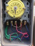
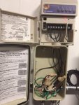
Even though, the licensed electrician should know this, I was just curious if anyone knows how the SWG Control Box is wired into the Intermatic Timer. He will be here in a few days to hook up the heat pump. Below are some pictures.

I picked this up on line, on how the SWG is configured.

• 240 Volts AC- Green to ground and 2 red wires to # 1 and # 4

• 120 Volts AC Loosen # 2 and # 3 and remove the 2 stack jumpers and move one jumper up and one jumper down. To apply 120 volts AC, attach 2 wires, normal black and white or red and white to terminals 1 and 4. Aqua Rite on left side and Pro on right side.

• Connect SWG # 8 bare wire to bonding on bottom on control box. Bonding system bare wire – bottom on SWG cabinet. Bonding wire to of plumbing wire.

Now, there should be a total of 3 wires. Anyone know how they are set up. Pictures of timer put together.
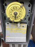
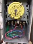
Timer # 2.jpg

Timer # 1.jpg

Left side is power to fuse box with shut off switch and the right goes to the 2 HP Hayward Pump.
 
Re: SWG Control Board Hook up to the Intermatic Timer

Swampwoman:

That would be great. Here is a more clear picture. The red is terminal # 3. Blue is terminal # 5. And green, the ground, I believe is terminal # 1. The pump is on the right. Pump is bonded and grounded.

The left side is the wiring that goes to the switch below the timer to shut off everything. Have no idea about other 2 other green wires. One is grounded to the box itself. Assuming the SWG wires will follow the pattern to the right. The more I look at the timer, the more confused I am. Although, I can definitely swap the wiring out in the future as it is already set up. I heard timers last anywhere from 5 years to 25 years. We will find out on Monday.

Box.jpg
 
Re: SWG Control Board Hook up to the Intermatic Timer

Okay, this may not be helpful at all, now that I looked at mine ;)

So, my green and black come in from the right side Aquarite swg and connect to the Square D via that conduit you see coming into the box). One black runs up into I believe te 5th position of the controller...that communicates like a deadman's switch (on/off only) and the rest I control by scheduling.

My recollection is that the Hayward Manual has a good schema describing the electrical.
And just so you know, Intermatic has always been good in terms of support...so if you give them a call, you'll get better and precise intel ;)

image.jpg
 
Re: SWG Control Board Hook up to the Intermatic Timer

Swampwoman:

Thanks for your help. I really have to let the electrician figure this one out. The issue with electrical wiring is the color may not tell the whole store. I want to get the SWG going at this point and the heater. Appreciate all your help and effort.

I do have about 12 gallons of 12.5% bleach left, but I am trying to clear my neighbors pool up. He has a chlorinator and a CYA of 70, but not following the rules of the game. So, it looks like the bleach is going down that way. Good news is that I will be reimbursed for the bleach!
 
Re: SWG Control Board Hook up to the Intermatic Timer

Swampwoman:

Update. The wiring was easy. The 3 wires out of the control box (Green is ground) and the other 2 wires are hot. If you go back to my timer, the load(s), # 3 and # 5 are hot. The ground is in the middle all the way back.

Luckily, I had a bonding wire long enough to start from the control box of the cell to the heater and back to the bonding system. He did a real nice job in putting everything together. 2.5 hours I was up and running. Programmed the salt cell and the reading is 2,800, which varies slightly from other.
 
Let's all get on the same page here. Intermatic timers have only 4 terminals. The ground terminal to the left is not numbered. Neither is the one in the back. I do not know why you have 3 wires from the electric supply. Only one is required. The hot terminals are 2 and 3 ( supply ). The switched terminals ( load ) are 2 and 4. The white wires are the time clock which is always on. Why they use white wires which is Neutral (not hot) in the electric world I haven't found an answer to in 45 years.

45 year licensed master electrician.
 
Cavie, the master electrician who wired mine only has 30 yrs under his belt, so he's your junior ;) But in the case of my wiring, it is via remote controlling the heater, pump and swg and has different ports assigned to each, and in the case of the 240 pump, explicit mfg directions as to what goes where. He talked to Intermatic while doing it to make sure it was right, so my hunch is that it's right.

The takeaway is that there may be some instances where its necessary to follow a particular scheme. I'm not sure which set up you're referring to in your comment so please feel free to explain.
 
The takeaway is that there may be some instances where its necessary to follow a particular scheme. I'm not sure which set up you're referring to in your comment so please feel free to explain

My original wiring for the timer was done during the pool build. The subsequent was done to add the SWG. I actually have a shut off switch at the pump for everything, and a separate one for the light. Everything, of course leads to the fuse box. I doubt your schematic or mine is wrong in nature.
 

Enjoying this content?

Support TFP with a donation.

Give Support
Thread Status
Hello , This thread has been inactive for over 60 days. New postings here are unlikely to be seen or responded to by other members. For better visibility, consider Starting A New Thread.