I just replaced my old Hayward T-15 cell with the exact same model. (setting is correct in my diagnostics) When I first started running the pool after replacing it the chlorinator would shut down with the dreaded High salt/Amps message. This was no shocker, as I am pretty sure when most chlorinators start to fail and have low salt readings.... we all add salt. However, after replacing a lot of water - the salt level of my pool was tested today and was 3400... which should be in range, and not kick off the chlorinator. I noticed the other thread with this problem got highjacked by the "No cell power' fix... which does not fix the problem of high amps, but no amps. Has anyone had any success getting rid of the high amps (10.5) reading after installing a brand new cell. I know the maximum amps the T-15 can handle is 10 before it shuts off - I don't want to think I need to replace the PCB Board. When I kick the chlorinator on, the reading says 1900..... but I know that reading is not correct. I also get 1900 as my instant salt check number.
High Salt/Amps reading on brand new Hayward T-15 cell
- Thread starter LadyFixer
- Start date
You are using an out of date browser. It may not display this or other websites correctly.
You should upgrade or use an alternative browser.
You should upgrade or use an alternative browser.
- May 3, 2007
- 16,975
- Pool Size
- 20000
- Surface
- Plaster
- Chlorine
- Salt Water Generator
- SWG Type
- Hayward Aqua Rite (T-15)
People have reported that the "No Cell Power Fix" does indeed fix the high amps problem as well. See here:
Aqua Logic Salt Too High - Cholrinator Off High Salt/Amps
But also double check that the setting in the AquaLogic is for the T-15 and not the T-9 cell.
Aqua Logic Salt Too High - Cholrinator Off High Salt/Amps
But also double check that the setting in the AquaLogic is for the T-15 and not the T-9 cell.
I have done the K-1 fix for the no cell power. That is the thread that was highjacked by the no cell power fix.......granted that works when you have zero amps..... but does nothing when your amps are too high. I did give it a try anyway (just in case)... but it did not do anything. I am certain those reports of it worked were from others with no cell power... as that is where I found the fix also. My voltage is reading -40.62 after waiting one hour to speak to Hayward. They told me my circuit board is bad. Not ready to give up hope yet.
- May 3, 2007
- 16,975
- Pool Size
- 20000
- Surface
- Plaster
- Chlorine
- Salt Water Generator
- SWG Type
- Hayward Aqua Rite (T-15)
Did you read the thread starting here: Aqua Logic Salt Too High - Cholrinator Off High Salt/Amps - Page 4
This person had the high salt warning re-soldered K1 and it worked for them. I have read other places that the K-1 solder joint causes one of two issues. No Power OR high salt but it seems to the cause for both. But the next poster, it did not work so hit and miss.
This person had the high salt warning re-soldered K1 and it worked for them. I have read other places that the K-1 solder joint causes one of two issues. No Power OR high salt but it seems to the cause for both. But the next poster, it did not work so hit and miss.
Meadow
0
My voltage is reading -40.62 after waiting one hour to speak to Hayward. They told me my circuit board is bad. Not ready to give up hope yet.
Is the -40.62 a typo? Why the negative sign? Under normal circumstances, Hayward SWG should not exceed 31 VDC when the switch is in OFF position or when cell is not generating. Try to reseat the Display board and make sure the pins are inline with the mating connector in the motherboard.
It was not a typo... it now reads +40.62...... earlier it showed -40.62. The voltage alternates between -40.62 and +40.62 every other time I try to turn it on. I am also not getting a proper salt reading. It is stuck on the 1900 from prior to replacing the new cell. Instant salt shows 1900 also - which is not accurate. I realize the salt readings are averaged over a 24 hour period, so figured this was just because the chlorinator is off. Could the voltage issue be the thermistor on my board? Or a power relay? I think I am going to order a new power relay..... as it seems that could be the reason the voltage is so wacky. Any thoughts?
- May 3, 2007
- 16,975
- Pool Size
- 20000
- Surface
- Plaster
- Chlorine
- Salt Water Generator
- SWG Type
- Hayward Aqua Rite (T-15)
The polarity should switch every time the unit cycles so that part is normal. However 40v is way too high. That is probably why the salt reading and the amps are too high. If you have a volt meter you could measure across the red and black wires that come from the rectifiers and see what the voltage reads there. If it is normal, then it is likely to be an issue on the board. If it is too high, then it could be a problem with the transformer.
Meadow
0
hmmm...ok! I just read the thread you were referring to and I'm surprised, others with K1 relay issues had reported the same excessive voltage readout too. Sadly, I have not perfected my troubleshooting skills via internet!
I have been wanting to snag one of the "for parts/not working" PCB for experiment but looks like they are HOT item. I couldn't find any copy of the AQR schematic diagram either!
But if I have a known working T-cell and has no knowledge of electronics, I might have to consider the following options to get me up and running.
1. For $45 -55 + shipping, a seller in eBay will repair your AQR PCB + 12 months warranty. Seller's feedback is 100% last time I checked.
2. Buy a replacement AQR motherboard that support T-15 cell.
The choice is yours, Good luck!
I have been wanting to snag one of the "for parts/not working" PCB for experiment but looks like they are HOT item. I couldn't find any copy of the AQR schematic diagram either!
Why not desolder and remove the relay from the PCB to perform the relay functional test before wasting your time and money?I think I am going to order a new power relay..... as it seems that could be the reason the voltage is so wacky. Any thoughts?
But if I have a known working T-cell and has no knowledge of electronics, I might have to consider the following options to get me up and running.
1. For $45 -55 + shipping, a seller in eBay will repair your AQR PCB + 12 months warranty. Seller's feedback is 100% last time I checked.
2. Buy a replacement AQR motherboard that support T-15 cell.
The choice is yours, Good luck!
Last edited:
Why not desolder and remove the relay from the PCB to perform the relay functional test before wasting your time and money? But if I have a known working T-cell and has no knowledge of electronics said:So I found the relay on Amazon - for a total of 10.00 it is on its way to me..... it is so dang hot out by my pool equipment it is almost unbearable to work out there! The heat may have played a part in the issue! I did try and resolder the back of the relay as I did see some burn marks on it, I did a poor job so am going to actually redo it... when the sun is gone!
I will certainly take a look on EBay if I can't remedy this! Or I will have my own PCB experimental board if I buy a new one! Thanks!
- - - Updated - - -
measure across the red and black wires that come from the rectifiers and see what the voltage reads there. If it is normal, then it is likely to be an issue on the board. If it is too high, then it could be a problem with the transformer.
I will get the voltage meter and check that. Thanks!
- May 3, 2007
- 16,975
- Pool Size
- 20000
- Surface
- Plaster
- Chlorine
- Salt Water Generator
- SWG Type
- Hayward Aqua Rite (T-15)
Definitely fix the solder joint first. That is the easiest and cheapest to try first. Cold solder joints cause all sorts of issues.So I found the relay on Amazon - for a total of 10.00 it is on its way to me..... it is so dang hot out by my pool equipment it is almost unbearable to work out there! The heat may have played a part in the issue! I did try and resolder the back of the relay as I did see some burn marks on it, I did a poor job so am going to actually redo it... when the sun is gone!
Also make sure there is not a break in the circuit board trace. Some have use a wire to bridge the gap from the relay to the trace.
Meadow
0
^what he said and I couldn't agree more with Mark!
@Lady, do yourself a favor! Take pictures of the wiring connections (label if necessary), disconnect all the wiring from the PCB. Carefully inspect/fix the PCB in a controlled environment for your own comfort. Having to flip the PCB over and over with all the wires tied up can often lead to another potential issue.
@Lady, do yourself a favor! Take pictures of the wiring connections (label if necessary), disconnect all the wiring from the PCB. Carefully inspect/fix the PCB in a controlled environment for your own comfort. Having to flip the PCB over and over with all the wires tied up can often lead to another potential issue.
Definitely fix the solder joint first. That is the easiest and cheapest to try first. Cold solder joints cause all sorts of issues.
Also make sure there is not a break in the circuit board trace. Some have use a wire to bridge the gap from the relay to the trace.
I tried soldering there again. Nada. So I think I will wait til my relays get here - I will for sure check to see if there is a break in the trace - doesn't appear to be....However, I am not having much luck with this lately! Had one pool issue after another lately - !!
- - - Updated - - -
^what he said and I couldn't agree more with Mark!
@Lady, do yourself a favor! Take pictures of the wiring connections (label if necessary), disconnect all the wiring from the PCB. Carefully inspect/fix the PCB in a controlled environment for your own comfort. Having to flip the PCB over and over with all the wires tied up can often lead to another potential issue.
Totally agree! I am going to remove the board completely when I get the relays in.... so I can work in the air conditioning! Shade temp by my pool equipment is 116 today.... it is a vortex of hot air!!! It is like the Vegas hotel hot spots that burn people! The shade temp on my screened porch is 89...... I didn't want to disconnect everything til I gave one last Hail Mary for a quick fix. Trying to keep my pool running since I have had to add a few things due to the lack of chlorine being generated.
- May 3, 2014
- 58,589
- Pool Size
- 6000
- Surface
- Fiberglass
- Chlorine
- Salt Water Generator
- SWG Type
- Pentair Intellichlor IC-40
Trying to keep my pool running since I have had to add a few things due to the lack of chlorine being generated.
Add bleach. Use Poolmath to determine how much. Treat this a non-SWCG pool until you get it fixed.
High Voltage - High Salt/Amps FIXED!
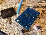
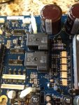
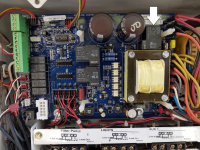
So my new relays came in ($10.00) - and I had some time this morning to completely take the circuit board out. Interestingly, the new burn marks on the back of my board are the same exact power relays as the relay which is the K1 fix. The burn marks were identical to what you see with the no cell power burn on K1. I had previously tried to resolder these with the board in place... in ridiculous heat..... with no success. While in the process of replacing the relays, I decided to just resolder each of the 5 pins on both relays - as I was having trouble getting a little solder off a couple pins to pull out the first relay without effort. I resoldered all the pins... popped the board back in. VOILA! My pool is now running at +25.80 v and 6.69 Amps. I didn't need the new power relays - but I didn't want to pull the whole board out and discover I did! Whoop ! Whoop!


Now on to my new pool problem..... AGH!
So my new relays came in ($10.00) - and I had some time this morning to completely take the circuit board out. Interestingly, the new burn marks on the back of my board are the same exact power relays as the relay which is the K1 fix. The burn marks were identical to what you see with the no cell power burn on K1. I had previously tried to resolder these with the board in place... in ridiculous heat..... with no success. While in the process of replacing the relays, I decided to just resolder each of the 5 pins on both relays - as I was having trouble getting a little solder off a couple pins to pull out the first relay without effort. I resoldered all the pins... popped the board back in. VOILA! My pool is now running at +25.80 v and 6.69 Amps. I didn't need the new power relays - but I didn't want to pull the whole board out and discover I did! Whoop ! Whoop!


Now on to my new pool problem..... AGH!
VAChuck
New member
Thanks to this thread I just saved $819 on a new goldline board. Cheapest one I could find with a quick internet search. I had the exact symptoms described by LadyFixer and I just added some solder to the bad looking pin on the back of the K1 realay. Working great now. Any idea how long this fix will last? My cell is about 9 months old.
- May 3, 2007
- 16,975
- Pool Size
- 20000
- Surface
- Plaster
- Chlorine
- Salt Water Generator
- SWG Type
- Hayward Aqua Rite (T-15)
One thing you can do to help with the longevity of the board is to keep the salt level on the lower end of the acceptable range. This reduces the current in the cell which in turn reduces the board temperatures.
Xer Doctor
New member
what is K1 relayThanks to this thread I just saved $819 on a new goldline board. Cheapest one I could find with a quick internet search. I had the exact symptoms described by LadyFixer and I just added some solder to the bad looking pin on the back of the K1 realay. Working great now. Any idea how long this fix will last? My cell is about 9 months old.
- May 3, 2007
- 16,975
- Pool Size
- 20000
- Surface
- Plaster
- Chlorine
- Salt Water Generator
- SWG Type
- Hayward Aqua Rite (T-15)
Thread Status
Hello , This thread has been inactive for over 60 days. New postings here are unlikely to be seen or responded to by other members. For better visibility, consider Starting A New Thread.


