
I am replacing my old pump with a Pentair Whisperflo pump Model WFDS-24 that is set up for 115V. It is a 1 HP pump with a 2 stage selection(Hi-Low) switch on the back of the pump. The wiring diagram on the pump is illegible. Can anyone tell me how to wire it to the appropriate terminals?
Additional info:
My wiring coming from the breaker is 115V Black, White, and ground and tests at 115V. It is connected to a 20 amp breaker that I am changing out to a GFCI breaker. I will also be adding a new copper grounding rod since our pool sidewalls, pump and heater never had an additional ground but relied on only on the house supplied wiring ground. Our pool was installed in 1994, inground 16X32 sport pool, concrete floor, steel sidewalls and vinyl liner( new 2 years ago). 5 years ago I replaced all plumbing lines to the pool, that was old 1" vinyl tubing leaking everywhere. The GFCI outlet that the pump was plugged into did'nt disconnect when pushing the test button the other day, which has precipitated adding the grounding rod and GFCI breaker.
I will include 2 photos to hopefully make things easier.
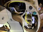
The top spade terminal (with nothing attached) is marked 1.
The next terminal where the yellow wire is attached is marked 2.
The last terminal where the white wire is attached is marked 3 and 4.
Additional info:
My wiring coming from the breaker is 115V Black, White, and ground and tests at 115V. It is connected to a 20 amp breaker that I am changing out to a GFCI breaker. I will also be adding a new copper grounding rod since our pool sidewalls, pump and heater never had an additional ground but relied on only on the house supplied wiring ground. Our pool was installed in 1994, inground 16X32 sport pool, concrete floor, steel sidewalls and vinyl liner( new 2 years ago). 5 years ago I replaced all plumbing lines to the pool, that was old 1" vinyl tubing leaking everywhere. The GFCI outlet that the pump was plugged into did'nt disconnect when pushing the test button the other day, which has precipitated adding the grounding rod and GFCI breaker.
I will include 2 photos to hopefully make things easier.
The top spade terminal (with nothing attached) is marked 1.
The next terminal where the yellow wire is attached is marked 2.
The last terminal where the white wire is attached is marked 3 and 4.

 Welcome to TFP!!!