10 Day Old IC-40 Just Went Dark

Shoot, I don't have any wire in front of me just now to guesstimate. But 16 would be more than enough, if you can reasonably get it soldered to the pins. Remember, the bigger the wire, the more heat you would need to solder it. 16 can power several 100W bulbs (like a dozen!), and that little board is not that. So if you are fumbling with 16, going a little smaller will be fine. If you can fit 16, it is plenty enough.

My drawing indicates solid copper wire. It's just easier to work with and solder. If you're talking stranded 16, that can sometimes be a bear to get solder to flow into it. I would use a smaller wire, solid copper, and tin it with solder first. The pins are already tinned. Then I would mechanically hold the wire in place, touching the pin (not even necessarily wrapped around the pin, if there is not room to do that). Then just a quick touch of the iron and solder will make a good electrical connection.

The wrapping is kinda a back up. The solder is doing the electrical work, the wrapping is mechanical, just making the connection physically stronger.

For reference: I'm running POE cams with ethernet cable. That's about 40V, same as that IpH board. That wire is probably ±22G, and my cams use way more power than that IpH board.
Insanely helpful, thanks Dirk. 🙏👍✌️
 
Shoot, I don't have any wire in front of me just now to guesstimate. But 16 would be more than enough, if you can reasonably get it soldered to the pins. Remember, the bigger the wire, the more heat you would need to solder it. 16 can power several 100W bulbs (like a dozen!), and that little board is not that. So if you are fumbling with 16, going a little smaller will be fine. If you can fit 16, it is plenty enough.

My drawing indicates solid copper wire. It's just easier to work with and solder. If you're talking stranded 16, that can sometimes be a bear to get solder to flow into it. I would use a smaller wire, solid copper, and tin it with solder first. The pins are already tinned. Then I would mechanically hold the wire in place, touching the pin (not even necessarily wrapped around the pin, if there is not room to do that). Then just a quick touch of the iron and solder will make a good electrical connection.

The wrapping is kinda a back up. The solder is doing the electrical work, the wrapping is mechanical, just making the connection physically stronger.

For reference: I'm running POE cams with ethernet cable. That's about 40V, same as that IpH board. That wire is probably ±22G, and my cams use way more power than that IpH board.
I think I used 12 gauge marine grade wire. 😂...definitely overkill but I had it leftover from when I rebuilt my boat, so I figure it was good enough for this application. Lol
 
  • Like
Reactions: Brushman
I'm a Dufus, I should just check the printed awg on the existing wires and match that right? Rookies are a pita.
Sorry, I may have misunderstood. If you're going to use a jumper between the reds and blacks, like LP did, then the gauge of that wire must match (or exceed) the gauge of the reds and blacks. I don't know if that is 16 or not. If you solder or wire nut them together, then you don't have to think about that. LP chose to use that short jumper, I wouldn't have, I would have just soldered the exiting reds together, and then the existing blacks.

I was referring to the gauge of the wire that gets soldered to the pins on the board. That wire can be a much smaller gauge than the existing reds and blacks. Those jumper wires will no longer be carrying the current that feeds the IntelliChlor, they only need to carry enough to power the circuit board and its components. 16 is not needed for that. I'm not sure how small that wire can be, but 18-22 would probably be OK. The thicker that wire is, the harder it will be to solder, which means the greater the risk of unsoldering the pins from the board.

The current that feeds the IC will then be going through the new splice, not through the old white connector and the traces of the circuit board. That is the fix. To create a new, more robust path for all the IC's current, away from the board... that is what stops the pins in the white connector from ever melting the connector again.

The white and green wires, even though sized the same, don't carry anywhere near the same amount of current. Which is why we've never seen their pins melt. I suspect the same gauge is used for those wires because that's how the cables are manufactured: four like wires. To be thorough, you don't splice the whites and greens together, they must remain as is.

Let me know if that's not all clear.
 
Here's some more data for you:

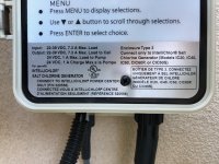
intellipH voltages.jpg

and...Screen Shot 2024-04-26 at 1.19.35 PM.png

The IpH specs are telling us that the IC can pull up to 7.3A (probably less for an IC40, but let's say 7.3). The chart above (if the ol' internets is to be trusted) is indicating that a 14 G wire to jump from red to red and black to black should be sufficient. 12 G is more than enough, but 16 is not.

Also in the spec you can see that the IpH pump motor might draw up to 1 amp, so I misspoke a bit, because that current runs through the board, and so will run through the new, little jumpers. It's not just the current of the board that must be satisfied by the little jumpers, but the pump motor, too (sorry, I forgot about that). The internets doesn't seem to agree, but I saw a spec as high as 7A and as low as .92A for a 22G wire. So maybe stay away from 22G and go 20 G or 18 G for the little jumpers.

This is what I would use. You can buy it by the foot at Lowes. It's cheap and easy to work with:


FYI: LP is really the pioneer for this particular fix. I fixed my IpH before I had hashed this all out with Ogdento and LP and others, and have all eight big, fat wires soldered directly to the board (definitely would not recommend that!). I cut off the white connector, and didn't need any jumpers or any other lengths of wire of any gauge. I just used the existing wires, so have never faced these particulars.

BTW, if you're going to use jumpers between the reds and blacks, there's probably enough slack to cut them right out of the middle of the existing wires, so that would assure you of using the correct size! Or, like I said, don't use any and solder the big fat wires directly to each other, with the little door bell wire coming off of that same solder blob.
 
Last edited:
  • Like
Reactions: Brushman
Here's some more data for you:

View attachment 567816

and...View attachment 567817

The IpH specs are telling us that the IC can pull up to 7.3A (probably less for an IC40, but let's say 7.3). The chart above (if the ol' internets is to be trusted) is indicating that a 14 G wire to jump from red to red and black to black should be sufficient. 12 G is more than enough, but 16 is not.

Also in the spec you can see that the IpH pump motor might draw up to 1 amp, so I misspoke a bit, because that current runs through the board, and so will run through the new, little jumpers. It's not just the current of the board that must be satisfied by the little jumpers, but the pump motor, too (sorry, I forgot about that). The internets doesn't seem to agree, but I saw a spec as high as 7A and as low as .92A for a 22G wire. So maybe stay away from 22G and go 20 G or 18 G for the little jumpers.

This is what I would use. You can buy it by the foot at Lowes. It's cheap and easy to work with:


FYI: LP is really the pioneer for this particular fix. I fixed my IpH before I had hashed this all out with Ogdento and LP and others, and have all eight big, fat wires soldered directly to the board (definitely would not recommend that!). I cut off the white connector, and didn't need any jumpers or any other lengths of wire of any gauge. I just used the existing wires, so have never faced these particulars.

BTW, if you're going to use jumpers between the reds and blacks, there's probably enough slack to cut them right out of the middle of the existing wires, so that would assure you of using the correct size! Or, like I said, don't use any and solder the big fat wires directly to each other, with the little door bell wire coming off of that same solder blob.
So you all got me thinking about what I did so I went down and pulled the IPH off its storage shelf (yeah the pool guy hasn’t opened his pool yet). For the red and black jumpers I used 14 gauge marine grade wire. For the blue wires that I ran from the back of the connector I used 16 gauge marine grade wire. @Brushman you shouldn’t really worry about space and working in the unit. By removing 7 screws (3 for the faceplate, 4 for the intellichlor connector) and gently releasing the 2 wire plug for the pump from the case, you can pull everything out of the case and work on your bench.
 
I've gone back and re-read multiple threads to try to avoid asking, but to be sure, I'm stuck asking anyway ...
If you're going to use a jumper between the reds and blacks, like LP did, then the gauge of that wire must match (or exceed) the gauge of the reds and blacks ... the wire that gets soldered to the pins on the board ... can be a much smaller gauge than the existing reds and blacks.

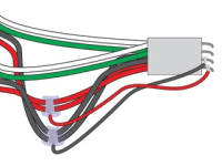
First off, this diagram below is not what you did or your first pass, but instead pictures the "LP Jumper Approach" right?
1714168448753.png


The LP Jumper Approach is what I want to do, largely because it cuts my "must solder" down from 4 to 2. I've watched a series of YouTubes on soldering technique and a lot of if is familiar so it should go fine, but still like the idea of only having to solder twice on or around the board, as pictured above. As you noted, the other stuff I can solder or connect otherwise and it should go fine either way.

By using the LP Jumper Approach (patent pending) pictured above, I think you've said I need to match or exceed the gauge of the original black and red wires pictured above. Is that correct? I've gone back and opened up the IpH box and to my surprise, neither of those sets of wires is labeled with identification or specifications. Some of the others are. Those aren't. Oh well. 🤷🏻‍♂️

But gauge I can figure out on my own by cutting a piece out and bringing it in to the hardware store to make sure I buy something at least that thick.

I think I'm going to "tin" the leads and jumper wires lightly to make soldering them together easier. If I understood everybody's comments, it's the danger of overheating those components when joining the jumpers to the existing pins that need to be carefully managed.

So I need to join the blacks coming in AND going out of the IpH together, the same with the reds, and to each of those I'll be adding a jumper to run down to the pins as pictured above, with the red jump getting seated on the "far inside" position of the four pins (which is labeled as position #1 on the picture of the PC board you took Dirk) and the black jump getting seated right next to that at position #2. I'll be going direct to the pins on the connector as LP did, not directly to the board as you did Dirk, but does that all sound right?

Sorry to ask if all this is obvious, but I've always been a measure 27 times and cut once guy. Way more work and confusing that way. 👍
 
For the red and black jumpers I used 14 gauge marine grade wire. For the blue wires that I ran from the back of the connector I used 16 gauge marine grade wire.
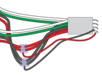
LP many thanks, those two sentences are short and sweet and make me realize that there's possibly a step involved here that I don't have my arms around yet. I think I understand this helpful diagram below -- but what confuses me is the fact that you have four "new" wires in play and I am conceptualizing only two based on Dirk's diagram.

1714170509083.png
 
LP many thanks, those two sentences are short and sweet and make me realize that there's possibly a step involved here that I don't have my arms around yet. I think I understand this helpful diagram below -- but what confuses me is the fact that you have four "new" wires in play and I am conceptualizing only two based on Dirk's diagram.

View attachment 567882
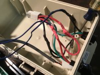
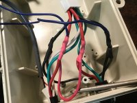
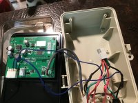
Dirks solution above is actually less work and more streamlined than mine. Where he shows the incoming red power leads wrapped with the smaller wire and soldered, I just added a large jumper wire between those two. Then I also added the smaller wire that runs to the backside of the connector. Perhaps these pics will show a little better.

IMG_0638.jpeg

IMG_0637.jpeg

You’ll note the screwdriver in the above pics is pointing to the jumpers I added.
Here is a shot of everything in one picture.

IMG_0639.jpeg
 
  • Like
Reactions: Brushman
I did not perform the "LP Jumper Approach" fix. Nor did I illustrate the fix I used. Ignore what I did. Do what LP did, as you state you want to.

By "little jumpers" I'm referring to the smaller diameter wires in my illustration. In LP's pics, the "little jumpers" are blue. You don't need 16G for that, and soldering 16G stranded wires to the pins is going to be more difficult than the 18G solid bell wire I recommended (link above to Lowe's product).

If you only want to solder those two "little jumpers" to the pins, that's fine, so you're overthinking all of the rest.

1. Purchase a foot of the bell wire (they come in a pair, so one white and one red).
2. While at Lowe's, purchase a small pack of large wire nuts. For this job, I recommend these. They are virtually designed for this fix.
3. WITH THE POOL PAD BREAKERS OFF,* remove the IpH from your system, and then its board and cables from the IpH chassis as LP describes. That's what I did and makes the work much easier.
4. At about half of their lengths, cut the two red wires and the two black wires. Now you'll have four of each color. DO NOT cut the green or white wires.
5. Strip the four red wires, the four black wires, and the two bell wires.
6. Twist all five red wires together (soldering optional) and apply one wire nut over all five wires.
7. Twist the four black wires together with the remaining white bell wire (soldering optional) and apply another wire nut over all five of those wires.

That's it. Forget about matching sizes of another set of wires between the reds and between the blacks, as LP did. You don't need those, nor do you need heat shrink. The DryConn Aqua Blue Weatherproof Wire Connectors will mechanically secure the wires together, and they contain a goo that will coat the splices and make them both water- and corrosion-proof. If you change your mind about soldering, you can solder the twisted wires together, and then put the wire nut over that.

8. Follow the original thick red wire through the white connector, and solder the remaining end of the red bell wire to its pin. Do so as close to the connector as possible, to avoid heating up the pin's connection to the board. I described how to do that in a previous post.
9. Follow the original thick black wire through the white connector, and solder the remaining end of the white bell wire to its pin. Same as you did for the red.
10. Reassemble the board and cables back into the chassis, put the IpH back where it was, connect the IpH to your pool controller (WITH THE BREAKERS OFF). Then turn on the breakers.
11. Start up the pump circuit that engages the IpH, BUT WITHOUT THE INTELLICHLOR CONNECTED. If nothing blows up, and the IpH display lights up, you're good to go. Turn the pad's breakers back off again, connect the IntelliChlor to the IpH, then turn the breakers back on and reengage the pump and IntellliChlor/IpH circuit.

* NEVER CONNECT OR DISCONNECT ANY POOL PAD ELECTRICAL COMPONENT WHILE THE BREAKERS ARE ON.

12. Go have a beer, 'cause you're done and you fixed your chlorine and acid systems.
 
Last edited:

Enjoying this content?

Support TFP with a donation.

Give Support
Update. The wire nuts I linked above are supposed to fit up to three #10 wires. That should probably work. But before you use one, and after twisting the wires together (and soldering if you decide to, which would increase the size), eyeball the size to see if the nut is big enough. If not, there is a bigger size. You might buy both, figure out which size you need, then return the set you don't use.

 
  • Like
Reactions: Brushman
Dirks solution above is actually less work and more streamlined than mine. Where he shows the incoming red power leads wrapped with the smaller wire and soldered, I just added a large jumper wire between those two. Then I also added the smaller wire that runs to the backside of the connector. Perhaps these pics will show a little better.

View attachment 567893

View attachment 567894

You’ll note the screwdriver in the above pics is pointing to the jumpers I added.
Here is a shot of everything in one picture.

View attachment 567897
Eureka! 👍👍👍
 
All's clear, you joined your reds with reds, blacks with blacks, and then it's the blues that both tie in (one to the reds, one to the blacks) and take that down to the pins. All good. The additional pictures and narrative were a huge help, thanks LP. ✌️
 
  • Like
Reactions: Lake Placid
If you only want to solder those two "little jumpers" to the pins, that's fine, so you're overthinking all of the rest.
Me, overthink? You, overdo? No way. 😆

Seriously, I'm really grateful for the help. And yes for sure, I usually overthink and yes, I usually overdo as well. Like you say, get it done once the right way. Or as I like to say, if it's worth doing, it's worth overdoing.

Really, really appreciate the generous guidance. I'm about to embark on my first soldering job in decades. Can't wait. And it's funny, just watching the refresher videos and seeing the work being done, I could suddenly smell solder again. That was a hoot.
 
  • Haha
Reactions: Dirk
and then it's the blues that both tie in (one to the reds, one to the blacks) and take that down to the pins
Just be aware: while LP happened to use the same color of wire for his jumpers to the pins, they are not interchangeable. The original red wires must be connected (via jumper) to the pin that is associated with the red wire, and same for the black side of things. The wires carry DC voltage, so there is a plus side (red) and a ground side (black). If you switch them up, you'll fry something.

Which is why I suggested above that after your repair you power up the IntellipH by itself, without the IntelliChlor connected, to confirm it works. Then later connect the IntelliChlor and power them both up. If by chance you get something wrong, better to only involve the IpH.
 
  • Like
Reactions: Brushman
Just be aware: while LP happened to use the same color of wire for his jumpers to the pins, they are not interchangeable. The original red wires must be connected (via jumper) to the pin that is associated with the red wire, and same for the black side of things. The wires carry DC voltage, so there is a plus side (red) and a ground side (black). If you switch them up, you'll fry something.

Which is why I suggested above that after your repair you power up the IntellipH by itself, without the IntelliChlor connected, to confirm it works. Then later connect the IntelliChlor and power them both up. If by chance you get something wrong, better to only involve the IpH.
I'll be doing both of those things precisely as you describe.

Had to order a couple of things I couldn't buy nearby so this surgery will have to wait till Monday.
 
  • Like
Reactions: Dirk
Or as I like to say, if it's worth doing, it's worth overdoing.
Well then you understand why I did it my way….bwwwwwaaaaaaahhhh 🤣. And it’s truly the only way 🤣🤣🤣🤣🤣🤣

Just be aware: while LP happened to use the same color of wire for his jumpers to the pins, they are not interchangeable.
100%! I had that wire laying around and I’m the only one that works on my stuff so I didn’t need color coded wire. The connector is physically molded in a way that it only allows itself to be plugged in one way. If you carefully observe the connectors design, it’s very easy to trace the reds and the blacks to the proper pin locations on the board side. Just take your time and double check everything and you’ll be just fine.
 
  • Haha
  • Like
Reactions: Brushman and Dirk
Well then you understand why I did it my way….bwwwwwaaaaaaahhhh 🤣. And it’s truly the only way 🤣🤣🤣🤣🤣🤣


100%! I had that wire laying around and I’m the only one that works on my stuff so I didn’t need color coded wire. The connector is physically molded in a way that it only allows itself to be plugged in one way. If you carefully observe the connectors design, it’s very easy to trace the reds and the blacks to the proper pin locations on the board side. Just take your time and double check everything and you’ll be just fine.
To be good at these kinds of projects, a little bit of OCD is our friend. And I will for sure carefully observe the connectors design and trace the reds and blacks to the proper location. This will be one of those "measure 9 times, cut once" moments.
 
That's not true. There are two ways to do it.
1. My way.
2. And the right way.
They just happen to be the same!! ;) Heh, heh, heh.
Amen. Like the old saying goes, I can always tell how smart someone is by how often they agree with me. 😜
 

Enjoying this content?

Support TFP with a donation.

Give Support