Hayward T-15 vs Pentair IC40 electrodes

757 YUKON

Member
Jul 12, 2023
10
Virginia Beach, VA
Pool Size
15000
Surface
Vinyl
Chlorine
Salt Water Generator
SWG Type
Hayward Aqua Rite (T-15)
Greetings from VA Beach to one of the best pool owners’ forums!

Just wondering if someone has info about the main electrodes total surface area comparison for Hayward T-15 and Pentair IC40 salt cells. Both cells are for pools up to 40.000 Gallons with very close chlorine gas production. A friend of mine has a Pentair equipped pool with IC40 salt cell. Recently his less than one season use salt cell has failed (the salt cell circuit board is completely dead with all LEDs off) and Pentair replaced (under warranty) the cell with a new one. He gave away that broken cell to me for educational purposes. The cell electrodes/plates inside are in a perfect condition. My plan is to get rid of the original IC40 circuit board and try to convert it to use IC40 cell body assembly with original electrodes with my AquaRite system as a backup cell.
 
Last edited:
Chlorine production for the T-15 is 1.47lb per day and the IC40 is 1.4...as you say, close in production.

Aside from production, warranty, reputation, and any automation you might have for compatibility, how would you use surface area to evaluate the cells?
 
Welcome to TFP.

Here are the dimensions of the Hayward plates:

T-15 has 13 Titanium Plates, 150 x 63mm. Produces 1.47 lbs/day.

T-9 has 13 Titanium Plates, 101 x 63mm. Produces 0.98 lbs/day.

T-5 has 7 Titanium plate, 150 x 63mm. Produces 0.735 lbs/day.

T-3 has 7 Titanium Plates, 101 x 63mm. Produces 0.53 lbs/day.

Hayward plates come from DeNora which is an Italian company.
 
I think that the plates are probably about the same.

Aquarite Cell Plates.​

Here are the dimensions of the Hayward plates:[14]

T-15 has 13 Titanium Plates, 150 x 63mm. Produces 1.47 lbs/day.

T-9 has 13 Titanium Plates, 101 x 63mm. Produces 0.98 lbs/day.

T-5 has 7 Titanium plate, 150 x 63mm. Produces 0.735 lbs/day.

T-3 has 7 Titanium Plates, 101 x 63mm. Produces 0.53 lbs/day.

Hayward plates come from DeNora which is an Italian company.[15]


Electrodes inside in a perfect condition. My plan is to convert it to use with my AquaRite system.
Convert it how?
 
The electrodes surface area I'll probably need for AquaRite salt reading correction. As I know a salt reading calculates based on cells voltage and a current consumption. I want to see if the IC40 electrodes/plates are similar to T-15
 
Last edited:
I think that the plates are probably about the same.

Aquarite Cell Plates.​

Here are the dimensions of the Hayward plates:[14]

T-15 has 13 Titanium Plates, 150 x 63mm. Produces 1.47 lbs/day.

T-9 has 13 Titanium Plates, 101 x 63mm. Produces 0.98 lbs/day.

T-5 has 7 Titanium plate, 150 x 63mm. Produces 0.735 lbs/day.

T-3 has 7 Titanium Plates, 101 x 63mm. Produces 0.53 lbs/day.

Hayward plates come from DeNora which is an Italian company.[15]


Convert it how?
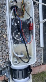
With a little effort and skills I've removed most of internal parts from IC40 and have an access to three spade connectors from the electrodes. It's a similar concept that T-15 has under black compound on the cell terminals.
 
Last edited:
No. I’ll not planning to make a new cell. I’m going to use a Pentair cell housing assembly with originally sealed electrodes and terminals and use Hayward T-15 cell original cable to connect it to IC40 plates terminals. The center electrode is with two white connected together wires from Aquarite control panel and other two on side electrodes are with two black wires in parallel.
 

Attachments

  • IMG_6027.jpeg
    IMG_6027.jpeg
    477.3 KB · Views: 10
  • IMG_6578.jpeg
    IMG_6578.jpeg
    394.4 KB · Views: 10
  • IMG_6580.jpeg
    IMG_6580.jpeg
    343 KB · Views: 10
  • IMG_6579.jpeg
    IMG_6579.jpeg
    391.2 KB · Views: 10
Last edited:
Moreover, the original Pentair flow switch that is installed on IC40 has four wires where two wires are for flow switch contacts and other two are for a built in thermistor that I can use for aquarite temperature monitoring (blue and red wires inside Hayward cable)
 

Attachments

  • IMG_6582.jpeg
    IMG_6582.jpeg
    396.1 KB · Views: 6
  • IMG_6581.jpeg
    IMG_6581.jpeg
    418.5 KB · Views: 5
Last edited:
  • Like
Reactions: JamesW

Enjoying this content?

Support TFP with a donation.

Give Support
Pretty cool idea.

Let us know how it works.

:goodjob:
Here's an update on my hobby project.

Before I've installed the modified IC40 cell in my pool piping, I did a preliminary workbench testing on the experimental cell using a cell cleaning stand filled with a pool water (tested in advance a water salinity with my Taylor 1766 and it shows 3100 ppm) connected to regulated 24VDC power supply. During a short test I had a decent number of bubbles coming out of produced gas from the cell open end. My workbench power supply showed 24VDC and the cell consumes 8.5Amperes.
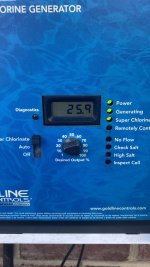
Then decided to install it and test it in a real-world condition with AquRite control (my control board has 1.59 version) connected and a pool pump running @1900 RPM. With T-15 cell setting selected on the control board my readings were (@65F water temperature): V=25.9V, I=8.34A and instant salinity went up to -5400 ppm (with my original T-15 previously installed was 6.7A and 3200 ppm), but AquRite kept generating with LED indication ON with no other faults. With that setup I left it running for three days. Except a high salinity reading seems to me it’s working. I know that electric current overload cut off for T-15 cell is 10A with High salt indicator LED on the panel.

So far don’t see any response from the forum’s members about data on Pentair IC40 cell plates dimensions. Something in T-15 and IC40 plates assembly is different. (I believe that a gap beetween IC40 plates a smaller or a working IC40 cell voltage is different) A time will tell.
 
Last edited:
  • Like
Reactions: JamesW
Most cut off at 8 amps.

There are a few models that cut off at 10 amps.

I would get the amperage below 7.4 amps to protect the circuit board.

Drop the salinity to about 2,800 ppm.
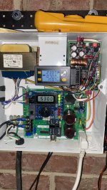
That what I thought also. And I did some improvements a bit in a different way. Im agreed with your point to reduce a pool water salinity to reduce a current consumption. As for now I don't want to dilute a pool water yet. And a fall rainy weather will do it for me. I did install a current limiter in DC power circuit after rectifiers before PC board.
 

Attachments

  • IMG_6656.jpeg
    IMG_6656.jpeg
    456.2 KB · Views: 6
Last edited:
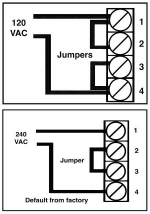
The power wires should be on 1 and 4.

Your wires are connected to #1 and #3.

Is your input power 120 or 240 volts?

View attachment 615461

View attachment 615460
As you can see it's connected to 120V receptacle. I know that is odd solution with 240VAC VSP, but for an extra protection in addition to a flow switch have installed a current sensing relay on my pool pump controller, that breaks a power to the SWG panel at low or no pump speed.
 
Last edited:
  • Like
Reactions: JamesW
Thread Status
Hello , This thread has been inactive for over 60 days. New postings here are unlikely to be seen or responded to by other members. For better visibility, consider Starting A New Thread.