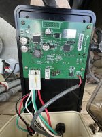
IC60 & IntelliPH

cactus_LV

Silver Supporter
Oct 16, 2020
117
Las Vegas
I know this is an old thread but thought it's probably not worth creating a new one for my question. My IntellipH just died and Pentair is hopefully replacing it. For the new unit I would apply fix #3 but was wondering which wire size is recommended to go around the connector? Also I noticed that it seems like Pentair discontinued the IntelliPH (the Pentair rep I spoke with pretended to not know)

Moved from here.
 

Attachments

  • IMG_5677.jpeg
    IMG_5677.jpeg
    506.4 KB · Views: 17
Last edited by a moderator:
  • Sad
Reactions: Dirk
I know this is an old thread but thought it's probably not worth creating a new one for my question. My IntellipH just died and Pentair is hopefully replacing it. For the new unit I would apply fix #3 but was wondering which wire size is recommended to go around the connector? Also I noticed that it seems like Pentair discontinued the IntelliPH (the Pentair rep I spoke with pretended to not know)
Interesting... still in their 2024 Product Catalog but no longer found on their website...
 
  • Sad
Reactions: Dirk
Also I noticed that it seems like Pentair discontinued the IntelliPH
Well that's one way to solve the problem. I don't imagine they sell enough of them. They severely limited the market for them when they engineered it to be dependent on an IntelliChlor.
 
For the new unit I would apply fix #3 but was wondering which wire size is recommended to go around the connector?
I drew #3 showing relatively small wires. They run off to the board, which by itself doesn't draw much power. And I'm showing how to strip the red and black wires without cutting them, and then using the small wire to bind them together. What's not shown is a big lump of solder joining all that together. So the small wire is only holding the two larger wires in place while you solder them. It would then be the solder that carries the current, so a large enough lump would do that job.

If, instead, you're going to bridge the wires with another wire, then that wire needs to be the same gauge as the red and black wires (I don't know what that is off hand). But then you'd still need a smaller wire to run to the contacts on the board. That's why I drew it the way I did. The smaller wire is enough for the board, and the solder would handle the current for the SWG.

If you're going to do this to a new IpH controller, then you don't really need those little jumper wires leading to the board, because nothing has melted yet. The existing wires will do that job. To simplify all this, you can just cut all the red and black wires and splice four reds together, and then the four blacks together, using a couple wire nuts or a WAGO connector. I didn't draw it like that because those types of connections are still prone to corrosion, which is my theory for why the original connector burned out, after collecting enough corrosion to cause overheating. The soldering solves for that: it's a corrosion proof connection.

If you don't want to solder, and use a mechanical connector instead, you might consider some electrical grease to help protect the connection from corrosion. I got this off of Amazon. You can use this on all the pins of the exterior connectors, too. That's what I bought it for.


But you might consider waiting until after the warranty on the first unit expires. Pentair should replace it up until then. After the warranty is done, then do your spices. Otherwise, Pentair could deny the warranty on the second one (which should carry over from the first one).
 
Just for giggles, see if the Pentair tech would be willing to leave you the old one. Worth asking, anyway. That unit could probably be repaired, so you'd have a back up (now that we might not be able to get them any more).
 
@Dirk thank you so much for the detailed response. I will try to keep the old one but I don't think mine can be repaired since it's not just the connector but also D3, D4 and the one next to that who got fried.
First I need to get a new one LOL Pentair wants to come out to check that it's not my electricians fault that it got fried. I will apply the fix to the new one then so I will just solder 4 blacks and the 4 reds together and apply the electrical grease to the connector.
 
  • Like
Reactions: Dirk
Oh, I see D3 and D4 now. Yep, we've seen that before. And sometimes that white component between them and the connector gets burned, too. That's a relay. I forget what D3 and D4 are doing, @ogdento knows. We never really determined if the D3 and D4 meltdown is directly related to the overcurrent problem that is frying the connector. But yah, that board is toast.

Good luck with the Pentair tech. Don't let him leave without giving you your new board. This is a very well known issue and had nothing to do with what an electrician might have done (especially if it ran fine for some time). I doubt he'll give you any grief. He'll know what happened, and it's not his money anyway.
 
  • Like
Reactions: cactus_LV
D3 and 4 are ESD Suppressors / TVS Diodes (part SMAJ6.0CA)... they can be replaced, along with the 8-pin comm chip to their right. If the board is toasty or burnt you might have to do a little re-work of the traces with wire or copper foil.
 
  • Like
Reactions: cactus_LV and Dirk