Pentair Mastertemp 250 24 VAC short keeps blowing fuse

Apr 21, 2018
26
Gainesville
Pool Size
20000
Surface
Plaster
Chlorine
Liquid Chlorine
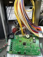
Hello! This is my first post ever but I’ve been searching and reading the forum for a while about all sorts of issues with my pool. I use TFP app to track and balance my pool chemistry and I love it. However, I’ve been having a problem with my heater. It’s a natural gas Pentair Mastertemp 250 bought in 2018 new. It is wired at 240V to the same breaker as my pump. It doesn’t have any automation control. It worked great until a month ago when I turned the breaker off to have work done on the pool plaster. Once the work was done and the pool was refilled I turned on the breaker and the pump started up fine but the heater was completely dead. Nothing lights up on the display and the LEDs are all off.

I’ve been trouble shooting the problem for 2 weeks with no success so I’m posting here to see if I can get some expert advice. I have followed the Pentair MasterTemp Electrical Troubleshooting Guide and there’s no problem with the power going to the heater. It’s 240v and yes, the correct (red) plug has been installed since day 1. The heater was working fine before turning it off. I did notice the fuse was blown so I went to Home Depot and bought 1 amp fuses which I realize the correct amperage is 1.25 amps but still I don’t think the issue is with the fuses.

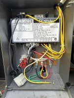
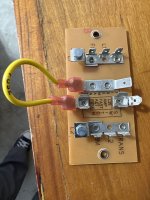
I’ve measured power to the Fireman Switch and it’s showing correctly 24 VAC at the terminals that go to the Main Board and 120 volts at the other two terminals.

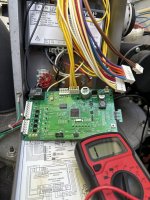
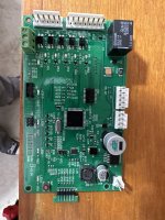
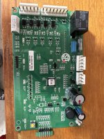
With the power off and all connectors to the Main Board disconnected, I’ve measured conductivity between the Fireman Switch terminals and ground to see if there’s a short on the 24 VAC circuit as it was suggested in a different post. I found conductivity when I plug in the J1 connector which tells me the Ignition Control Module or the wiring to it may be where the problem is. However, if I disconnect all connectors to the ICM, I still see conductivity which is telling me the issue is with the wiring or the Main Board. However, I have ordered a new board and the issue remains. There are no signs of the wiring having any damage (it looks brand new) so before I return the board or order a new ICM or wiring harness, I wanted to see if anyone can please provide me with some more troubleshooting techniques or advise.

Thank you for reading my post!
 
You could try removing the operating control board connectors at J1, J2 and J3 leaving only the 24V input to the control board and the firemans switch return to the control board at J7. Does the fuse blow? If so you have isolated the problem to the firemans switch and its wiring or the control board. If it doesn't blow, attach the connector at J1 and repower the heater. Does the fuse blow? If so, you have isolated the problem to the ICM or its associated wiring. The only connection at the ICM that should have zero or near zero ohms to ground should be the one lableled GND.

If the fuse blows with only the J7 connector in place, you can remove the J7 connector and check for continuity to ground on the 2 connections associated with the firemans switch. If they read as open, you have a problem with the control board.
The fuse doesn’t blow with J7 on. It does blow only with the J1 connection on. The problem is that the ICM is brand new so I don’t know if I got a dud or if the problem is with the wiring. Is there a way to test the ICM? You say “the only connection at the ICM that should have zero or near zero ohms to ground should be the one labeled GND” I don’t know if that means there should be no conductivity to any of the terminals on the ICM except for GND or the opposite. When I measure the ohms between ground and the 24 VAC connector on the ICM I get like 30 ohms so I’m not sure if that’s ok or a problem with the ICM.
 
You could try removing the operating control board connectors at J1, J2 and J3 leaving only the 24V input to the control board and the firemans switch return to the control board at J7. Does the fuse blow? If so you have isolated the problem to the firemans switch and its wiring or the control board. If it doesn't blow, attach the connector at J1 and repower the heater. Does the fuse blow? If so, you have isolated the problem to the ICM or its associated wiring. The only connection at the ICM that should have zero or near zero ohms to ground should be the one lableled GND.

If the fuse blows with only the J7 connector in place, you can remove the J7 connector and check for continuity to ground on the 2 connections associated with the firemans switch. If they read as open, you have a problem with the control board.
Thank you so much for your response!
 
Dumb question but … have you taken off all the covers and inspected all the wire harnesses to look for damage? Rats and other vermin love to setup their nests inside pool heaters and, for some reason, wire insulation is like Twizzlers to them … they love to chew on it.

Hope you track down the short soon. These types of electrical issues are always frustrating at best.
 
  • Like
Reactions: JamesW
Measure the ohms of each wire in J1 between the wire and GROUND. The only connection at the ICM that should have zero or near zero ohms to ground should be the one lableled GND.

You are looking to find the wire that is shorted, 0 ohms, to ground and blowing the fuse.

5E0B348D-3602-4E78-9D28-8E979849922F.png
 
Measure the ohms of each wire in J1 between the wire and GROUND. The only connection at the ICM that should have zero or near zero ohms to ground should be the one lableled GND.

You are looking to find the wire that is shorted, 0 ohms, to ground and blowing the fuse.

View attachment 463978
Thank you so much for your response. I will try this process today. I guess I will need to buy a new J1 harness since it seems to me that’s the problem. I will post what I find out. Thank you!
 
Helllo! Good morning!
I just did a round of testing (again) on the wiring for my heater. I measured the ohms between ground and the ends of the cables in J1 and there was none except for the GND wire which makes sense. I made a video that hopefully explains the issue I see better. Should there be ohms reading between the FS connector and ground?
 
In your video you are probing J7.

In post #3 you say the fuse does not blow with just J7 connected and J1, J2 and J3 unconnected to the board.

Then you say that the fuse blows when you have J7 and J1 connected with J2 and J3 not connected. That correct?

J1 connects the board to the ICM/Fenwal. That points to a problem with the J1 wiring or the Fenwal box.

Your focus is on the board when it should be on the Fenwal module and the wiring to it.

Get a bunch of fuses and disconnect all the wires at the Fenwal box. Then connect one set of wires at a time starting with just the 24V AC wire (yellow) and the GND wire.

Then F1, F2 (green) that powers the blower.

Then the lower orange wires that power the igniter starting from left to right with the wires and plug.

Then the TH, IND, VAL wires which control the gas valve.

You have to go through a process of elimination of the various Fenwal connections.

Lets see is @swamprat69 @ps0303 is around.

1669853356981.png
 
On J7 the left two wires connect to 24V AC on the transformer.

Check that you have 24V AC from the transformer.

A bad transformer can blow the fuse.
 

Enjoying this content?

Support TFP with a donation.

Give Support
In your video you are probing J7.

In post #3 you say the fuse does not blow with just J7 connected and J1, J2 and J3 unconnected to the board.

Then you say that the fuse blows when you have J7 and J1 connected with J2 and J3 not connected. That correct?

J1 connects the board to the ICM/Fenwal. That points to a problem with the J1 wiring or the Fenwal box.

Your focus is on the board when it should be on the Fenwal module and the wiring to it.

Get a bunch of fuses and disconnect all the wires at the Fenwal box. Then connect one set of wires at a time starting with just the 24V AC wire (yellow) and the GND wire.

Then F1, F2 (green) that powers the blower.

Then the lower orange wires that power the igniter starting from left to right with the wires and plug.

Then the TH, IND, VAL wires which control the gas valve.

You have to go through a process of elimination of the various Fenwal connections.

Lets see is @swamprat69 @ps0303 is around.

View attachment 464148
Thank you AJW22 I appreciate your help. I’d like to think that I can use the multimeter instead of a bunch of fuses. The breaker to the heater is at the other end of the house so it’s very time consuming to walk there and turn it off and on for the test procedure you’re suggesting. It makes sense to me that if I can measure conductivity to ground from the terminals to the fuse I can assume the fuse would blow if there was power correct?
I will follow the testing sequence of the ICM connectors as you describe with no power to the heater and see if I measure conductivity to the ground from the fuse connectors tomorrow morning and I’ll post what I find.

Thank you again!
 
@ajw22 I tried the process you suggested and I found that the fuse blown with all the connectors to the ICM unplugged. All the connectors to the main board were plugged in and the FS jumper was on. I’m using 1 am fuses from Home Depot which could be the issue. I just ordered 1.25 amp fuses from Amazon that will be arriving Monday. Does the 0.25 amp difference between the fuses matter?
 
@ajw22 I tried the process you suggested and I found that the fuse blown with all the connectors to the ICM unplugged. All the connectors to the main board were plugged in and the FS jumper was on.

Disconnect J1, J2 and J3. Does a fuse blow with just J7 connected?

Then have just J1 and J7 connected. Does the fuse blow?

Just have J1 and J7 connected and disconnect the wires from the Fenwal. Does the fuse blow?

I’m using 1 am fuses from Home Depot which could be the issue. I just ordered 1.25 amp fuses from Amazon that will be arriving Monday. Does the 0.25 amp difference between the fuses matter?

It should not but I never tried it with a 1A fuse.
 
Last edited:
Disconnect J1, J2 and J3. Does a fuse blow with just J7 connected?

Then have just J1 and J7 connected. Does the fuse blow?

Just have J1 and J7 connected and disconnect the wires from the Fenwal. Does the fuse blow?


It should not but I never tried it with a 1A fuse.
@ajw22 yes the fuse blew with just j7 connected
 

Attachments

  • image.jpg
    image.jpg
    558.4 KB · Views: 5
@awj22 I checked the fireman switch and it’s in perfect condition. I also checked the wires to the FS and they do not have conductivity to ground so I guess the issue is with the control board? I actually ordered 2 control boards from amazon. They are the same model as the original one but look slightly different. The part number is

sixcow 42002-0007S Control Board Kit & 472610Z Switch Membrane Pad for Mastertemp & Max-E-Therm Pentair All NA and LP Series Pool and Spa Heater Electrical Systems​


From Amazon.
 

Attachments

  • image.jpg
    image.jpg
    524.9 KB · Views: 3

Enjoying this content?

Support TFP with a donation.

Give Support
Thread Status
Hello , This thread has been inactive for over 60 days. New postings here are unlikely to be seen or responded to by other members. For better visibility, consider Starting A New Thread.