Hayward SWG install in a tight space

randytsuch

LifeTime Supporter
Mar 29, 2008
518
Los Angeles, Ca
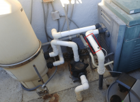
A little while ago, decided to convert to a SWG.
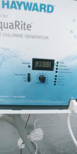
Settled on Hayward because I want to add a RS-485 interface to give me remote control capabilities, and Hayward SWG's seem to be good, I see recommendations here for them.
Planning to install over the long weekend.

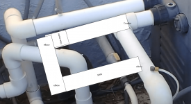
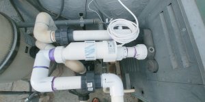
The red rectangle in the picture is the space I have for a SWG. Its less than 12" long between the elbows, so not enough.

I plan to cut around 7" of pipe in the middle, and add a couple elbows into a home made vertical type U shaped adapter.

Hayward wants 12" of straight pipe before the flow sensor, so planning to have elbow to 12" of straight pipe to flow sensor to two elbows (making the U) to SWG to elbow back into existing pipe.

I'll post a pic after I put something together so its clearer what I'm doing.

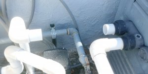
The gas line to the heater is under the pipe where I am installing, so I can't go straight down. I can go up, but it would be exposed to a lot of sun if I did that.
I think it would fit going down, at an angle toward the heater.

Could also install horizontally, then it would be over my pump.

Wondering what the experts here think about how I should install?

The control panel is going on the wall between the heater and filter, I rearranged the boxes yesterday to make the space, and even have mounting screws in the wall.

I also am documenting my install here

Thanks
Randy
 

Attachments

  • swg setup.PNG
    swg setup.PNG
    140.6 KB · Views: 40
I'm not sure I completely understand you plans, but a couple things to consider. If you loosen the union on the heater, you can clock the first elbow in any direction you want. That eliminates one 90 from the equation.

When the flow switch is mounted after the cell, the cell counts as the 12" required straight pipe.
 
Figure below is one option I was thinking of.

Mount it horizontally, where it would be over the pump. Flow sensor is at end of 12" of straight pipe to meet Hayward's requirement for positioning the sensor.

Option 2 would be vertically up. In that case, I can do as you suggest, rotate the elbow from the heater to point it up, and save an elbow and some gluing.

Option 3 would be to go vertically down. But I can't go straight down because gas line is under the pipe. So would have to go down at an angle. Advantage here is it would be mostly in the shade during the day.
Vertically up would be in the sun most of the day.

Hope this makes more sense now.

Randy
 

Attachments

  • swg setup 01.PNG
    swg setup 01.PNG
    237.1 KB · Views: 7
Is this a vertical install or horizontal. Hard to see from the picture if horizontal doesn't get in the way. For a vertical you need to be sure on which side the cell goes on, not sure of the spec if they want the cell on the uphill or downhill side.
 
Lots of options for plumbing. Here's one more. Clock the 90 off the heater back/up at a 45 degree angle to increase the horizontal length. You may gain enough length to fit the cell and flow switch on the upper horizontal. You'll have to play around with segment lengths to figure it out. Pardon the bad sketch, but you should get the idea:

1656625755979.png
 
Is this a vertical install or horizontal. Hard to see from the picture if horizontal doesn't get in the way. For a vertical you need to be sure on which side the cell goes on, not sure of the spec if they want the cell on the uphill or downhill side.
My figure was attempting to show a horizontal install. I don't think anything will get in the way, I'll check again when I get home though, before today I was just thinking vertical.

Hayward doesn't spec uphill or downhill that I saw in the manual.


Mike
Interesting idea, thanks for that one. Took me a min to see what you meant, but I get it now. I would need to raise the piece coming out of the ground though, if I understand the drawing correctly.

Randy
 
Couple things come to mind: I didn’t see a check valve between heater and cell (seems to be desirable to prevent anything corrosive generated by the cell from getting into he heater when the pump stops); if you have the room and don’t mind the look, a “Hartford loop” type of install with the cell vertical on the return side of the loop, and the top of the loop above the heater inlet creates a type of heat trap that will also reduce the chances of any water backflowing from cell to heater. Probably overkill, just some thoughts.
 
I didn’t see a check valve between heater and cell (seems to be desirable to prevent anything corrosive generated by the cell from getting into he heater when the pump stops)
There is no need for a check valve between a heater and a SWCG. There is nothing corrosive generated inside of a SWCG.
 

Enjoying this content?

Support TFP with a donation.

Give Support
There is no need for a check valve between a heater and a SWCG. There is nothing corrosive generated inside of a SWCG.
Ok, like I said, probably overkill. Temporary high pH from hydroxides and increased temp from cell & heater can lead to localized scale formation, but maybe not.
 
With my last plan, the SWG was going to get too close to my filter, so adjusted my plans.

Putting the flow meter on the heater input line.
First pic is the cuts in the existing pipe, 2nd is with flow meter installed. Also added a union to make it easier.
Also by some stroke of luck, because of the union on the filter, I could rotate the left end out of the way while I glued the middle part of the pipe into the flow meter.
And it doesn't leak. Small victories, first time I've attempted any plumbing related projects on the pool, not as hard as I thought it would be.
I also liked this separated things into two parts, so I was able to do the smaller easier part first.

Randy
 

Attachments

  • 20220702_130405_HDR.jpeg
    20220702_130405_HDR.jpeg
    428.8 KB · Views: 7
  • 20220702_102538_HDR.jpeg
    20220702_102538_HDR.jpeg
    272.8 KB · Views: 7
Finally finished installing my Hayward SWG.
Messed up and had to order a union to finish.
All good now, no leaks, and SWG seems to be working fine.

I'm trying to keep at the low end of salt at 2800 and ca at 250, will see how that goes.

For power to SWG, I added an burial rated wire to a 3 prong ac plug, and run to an outdoor smart switch.
I control pump on/off times and this switch through Home Assistant running on a pi, so easy to adjust run times.

I bought a rs-485 converter to see if I can setup to fully control the SWG, next on my project list.

Randy
 

Attachments

  • 20220712_195406.jpg
    20220712_195406.jpg
    241.5 KB · Views: 9
  • 20220712_195414.jpg
    20220712_195414.jpg
    168.8 KB · Views: 9
  • Like
Reactions: Newdude
Looks good! The shape and design of the cell looks the same as the CircuPool RJ-Series. The CP manual includes a recommendation to rotate the cell as shown in the image below when used with a VS pump. At low speeds, an air bubble can form at the top of the cell which can expose the top of the plates. Rotating the cell prevents air entrapment so the plates remain submerged.

NOTE: When using a Variable-Speed or Multi-Speed pump on a low speed setting, or for general circumstances where flow is less-than-adequate, the cell must be inverted in order to ensure adequate flow & efficient chlorine production.

1657720700704.png

Here's what mine looks like.

1657721189658.png
 
  • Like
Reactions: randytsuch
Thanks for the tip, will rotate it when I get home.

I was surprised I can run my VSP at my normal pump speed at 1200 rpm which only uses 68 watts of power. Expected to have to increase speed, but I just started the pump and all was good.
Even with my high electricity rates, looking at around $50 per year in increased electricity to run the pump longer to run the SWG. Will figure it out again after I dial things in.

Its running at 26.3 volts and 5.95 amps. I found a diagnostic manual online that gives the range as 22-26V and 3.1-8.0 Amps for the T-15 cell. My AC runs high so thats why I'm a little over the voltage.
But current seems good.

Same manual says the T-15 will shutdown at 10 Amps. Shows a High Salt warning at that point.

Randy
 
It looks like you'll have to run 8-10 hours per day (100%) to make up for daily FC loss during swim season. That's not bad. Take advantage of low RPM runtimes with the SWG.

When setting the minimum speed, find the speed at which the cell stops producing and add a couple hundred RPM as a buffer.

I'm on a SCE Time of Use plan. Wanna guess when I don't run my pump...

1657724756044.png

What's nice is I have free solar. The previous owners paid off a 20 year lease, so we have free electricity for 16 years. Since we moved in, we've generated more than we used.

Another sidenote, CP recommends that the fitting/wires on the flow switch is on top for horizontal installations. Looks like you can spin that when you work on the cell.

Best of luck!
 
Thread Status
Hello , This thread has been inactive for over 60 days. New postings here are unlikely to be seen or responded to by other members. For better visibility, consider Starting A New Thread.