Blown Motor?

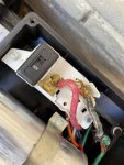
So when I was testing at pump with voltmeter, should both red-to-ground and black-to-ground shown same voltage? Assuming 230V, given the wire colors

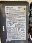
Note: Do not switch to 115 volts unless you are sure that the supply is really 115 or you will definitely burn up the motor.

I'm pretty sure that the original power was 230 volts because the wires are black and red.

If the original supply was 115 volts, the wires should be black and white.

I suspect that the power supply is damaged somewhere.

Was the old motor set to 115 or 230 volts?
 
Ok, I just went back to the first page and it looks like the pump is set up on 115 volts.

The subpanel has 230 volts coming in, so it doesn’t make any sense to run on 115 volts.

I would install a 20 amp gfci, 230 volt double breaker in the subpanel and run the pump on 230.

Right now, you have black and red going to terminal A in the timer. You would move the black wire to terminal 3 and the red wire to terminal 4.

The black wire on terminal 3 will go to one of the hot terminals on the new gfci breaker.

Note: Make sure that you know exactly what you’re doing before turning on the power.

You would need to run a white neutral to terminal A in the timer to the neutral lug in the new GFCI breaker. The wire can be small at 16 or 14 gauge since it will only power the clock.

The GFCI should come with a white pigtail, which will connect to the neutral bar in the subpanel.

What is the timer model number?
 
Last edited:
Ok, I just went back to the first page and it looks like the pump is set up on 115 volts.

The subpanel has 230 volts coming in, so it doesn’t make any sense to run on 115 volts.

I would install a 20 amp gfci, 230 volt double breaker in the subpanel and run the pump on 230.

Right now, you have black and red going to terminal A in the timer. You would move the black wire to terminal 3 and the red wire to terminal 4.

The black wire on terminal 3 will go to one of the hot terminals on the new gfci breaker.

Note: Make sure that you know exactly what you’re doing before turning on the power.

You would need to run a white neutral to terminal A in the timer to the neutral lug in the new GFCI breaker.

The GFCI should come with a white pigtail, which will connect to the neutral bar in the subpanel.

What is the timer model number?
 

Attachments

  • image.jpg
    image.jpg
    559.2 KB · Views: 1
When you say ‘looks like the pump is set up on 115 volts‘ what drove that observation? I have switch set to 230V on pump

With this motor setting (230V) confirmed, do we still need to add a gfci etc? Not sure why that fundamentally needs to change if I’m set to 230V on pump.

I will study your comments a little further - apologies for any redundancy. Been a long day

Ok, I just went back to the first page and it looks like the pump is set up on 115 volts.

The subpanel has 230 volts coming in, so it doesn’t make any sense to run on 115 volts.

I would install a 20 amp gfci, 230 volt double breaker in the subpanel and run the pump on 230.

Right now, you have black and red going to terminal A in the timer. You would move the black wire to terminal 3 and the red wire to terminal 4.

The black wire on terminal 3 will go to one of the hot terminals on the new gfci breaker.

Note: Make sure that you know exactly what you’re doing before turning on the power.

You would need to run a white neutral to terminal A in the timer to the neutral lug in the new GFCI breaker.

The GFCI should come with a white pigtail, which will connect to the neutral bar in the subpanel.

What is the timer model number?
 

Attachments

  • image.jpg
    image.jpg
    353.6 KB · Views: 1
Ok, it looks like the motor is wired for 115 volts. I don't know why that was done. You should be able to switch the voltage selector switch to 115 volts and the motor should work.

I would plan to change over to 230 volts as described in my previous post.
 
The red wire going to the motor is currently connected to terminal A with the black wire.

The black wire looks like it goes to the neutral bar in the subpanel (confirm please).

So, that makes the power supply 115 volts since you have a neutral and a hot.

I suspect that the motor originally was wired 230 volts and it probably got switched to 115 when the original motor was replaced.

It makes no sense to run on 115 when you have 230 available.

I would plan to switch over to 230 as soon as possible.
 
Hey James - you were correct. I switched pump to 115V and runs like a CHAMP. Thank you for sticking with me all day.

Regarding switching power supply to 230v can you tell me what’s the advantage to running that way vs the way I’m now running? I ask this question sincerely b/c I’m not a pro with electric. Am I losing out on power or unnecessarily over-drawing amperage?

If I didn’t do anything right away, is running in this fashion somehow detrimental? Forgive the dumb questions. Thanks for your help

The red wire going to the motor is currently connected to terminal A with the black wire.

The black wire looks like it goes to the neutral bar in the subpanel (confirm please).

So, that makes the power supply 115 volts since you have a neutral and a hot.

I suspect that the motor originally was wired 230 volts and it probably got switched to 115 when the original motor was replaced.

It makes no sense to run on 115 when you have 230 available.

I would plan to switch over to 230 as soon as possible.
 
Last edited by a moderator:
  • Like
Reactions: mknauss
It looks like you have a 230 volt, 40 amp, double pole breaker that only feeds one hot line.

That’s not the correct way to do it.

You could move the black wire connected to the neutral bar to the other open lug of the breaker.

Then, move the black wire in the timer from terminal A to terminal 3 and the red wire from terminal A to terminal 4.

Then run a 14 or 16 gauge white, stranded wire from the neutral bar in the subpanel (or the neutral lug on a gfci breaker) to terminal A in the timer.

Then, you will have 230 volts to the motor and you can switch to 230 volts on the selector switch.

The clock motor is 120 volts, so it needs to be connected to a neutral and a hot. The two small white wires go to the clock.

The 40 amp breaker is too big for the application and the breaker is supposed to be gfci by current code.

It will work like you have it now, but I would go with a 230 volt, 20 amp, gfci breaker and run 230 volts for optimum performance.

All you would need is a breaker and a short length of #14 or #16 stranded white wire.
 

Enjoying this content?

Support TFP with a donation.

Give Support
We are glad you have found our information helpful. Please, if you can, consider making a donation to TFP.
We are staffed by volunteers and are registered as an IRS 501 (c) (3) charity and donations are what keeps the forum operating without advertisements.

Support TFP!
 
Thread Status
Hello , This thread has been inactive for over 60 days. New postings here are unlikely to be seen or responded to by other members. For better visibility, consider Starting A New Thread.