Pump Electrical Issue

kafox001

Well-known member
Jun 10, 2019
130
New England
Pool Size
23000
Surface
Vinyl
Chlorine
Liquid Chlorine
Hello,

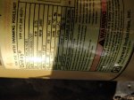
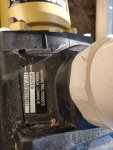
I am troubleshooting an electrical issue with my Hayward Super Pump (SP2607X10) where the cord/plug overheats and trips the thermal protection of my smart plug/timer (TP-Link Kasa KP-400). The pump motor itself doesn't seem to get too hot as I can hold my hand on it after it trips and its not burning.

This started at the end of last year when I went to unplug my old timer at the end of the season (Intermatic P1121) and realized the plastic on the timer has melted and I couldn't remove the pump plug from it. Figured it was a timer issue and got a new one for this year.

This year started off fine running the pump 24/7 to SLAM but after a few days, the new timer kept tripping and shutting off the pump.

So far I have tried:
1. Cleaning up the pump plug with sandpaper/steel wool to remove any possible corrosion
2. Replaced the electrical outlet (20 Amp, 125V outdoor GFCI)

After taking those steps, it only seems to trip once every couple days and seems random. I inspected the run back to the subpanel in my garage and it all looks good to me. From the subpanel its a 20 Amp breaker -> 12/2 nmc -> 20 Amp, 125V Outdoor GFCI -> KP-400 timer -> Pump Plug. I think the KP-400 timer is only rated for 15 Amps, but my pump states 15 Amps so shouldn't be an issue unless I am missing something.

Some pics attached, but let me know what my next steps in troubleshooting this should be. Thanks!
IMG_20200531_105840.jpgIMG_20200531_183508.jpgIMG_20200531_183517.jpg
 
Do you have any way to check the amp draw of the motor? Or have a friend that could?
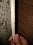
You said that you replaced the receptacle, but have you replaced the cord on the pump? The connection between the wires and the plug could be bad.
 
Do you have any way to check the amp draw of the motor? Or have a friend that could?
You said that you replaced the receptacle, but have you replaced the cord on the pump? The connection between the wires and the plug could be bad.

I don't think my multimeter will do that. Would something like this work?

I have not yet replaced the power cord. Would this be the correct one to get?
 
The meter you linked would work fine. You have to clamp the clamp around a single conductor to get it to read so that may be a little tricky,

As for the cord, while that one will work, I'd personally get a 12/3 awg and add the spade lugs to it. But if you don't have the tools to add the lugs, the one you linked will work.

If I am replacing the power cord anyways, could I carefully remove the outer jacket from my current cable and clamp around one of the conductors that way instead of trying to do it within the motor housing?

I think adding the lugs myself is a bit out of my comfort zone. I would constantly worry that they would come loose. I think I'll just stick with the 14 awg cable.

Is there anything else I can check to rule out electrical issues on the house side of things? The pump is only 4 years old whereas this circuit was likely installed decades ago and is original besides the receptacle I replaced. One thing that I forgot to mention is that this receptacle appears to have two grounds. One back to the panel as expected, but there is a second ground conductor in the box that is tied to the normal one and then connected to the GFCI receptacle. This second conductor goes directly down into the ground behind my filter and is in conduit. Unsure if this is (or was at one time) standard practice or could contribute to issues?
 
I think the KP-400 timer is only rated for 15 Amps, but my pump states 15 Amps so shouldn't be an issue unless I am missing

No circuit should be loaded at more then 80% of capacity. So a 20 amp CB should only have 16 amps of load. Your pump running at 15 amps is right at the max.

The timer is not made to be run at 15 amps continuously. That timer is unsuitable for a 15 amp motor use.

You never want to run any electrical equipment at 100% of its maximum specifications.

So the pump is always going to draw 15 amps? I thought that was just the max that it would draw, not that it would always be drawing 15 amps.

What should I use for a timer then? Is there a such thing as a 20 amp plugin timer?
 
So the pump is always going to draw 15 amps? I thought that was just the max that it would draw, not that it would always be drawing 15 amps.

What should I use for a timer then? Is there a such thing as a 20 amp plugin timer?
Yes. It is a single speed pump. It will draw 15A. As it ages, and things start to deteriorate, like bearings, it may draw more amps.

Also, what is the length of the wire run to the pump? If the run is too long, the voltage drop could be too high, causing higher amps. Measure the voltage at the pump with the pump running (need a load) and let us know the voltage. If it is less than 115V, then your amps are going to be high.

Also, the timer needs to be a 20A timer. Yes, they make 20A plug in timers.
 
Last edited:
So the pump is always going to draw 15 amps? I thought that was just the max that it would draw, not that it would always be drawing 15 amps.

A single speed motor, that you have, will always draw the same amps when running.

What should I use for a timer then? Is there a such thing as a 20 amp plugin timer?

Yes, there are 20 amp timers. However most consumer level timers are not made to take a continuous load at 75% of it's rating. They are made to switch lights and consumer appliances that draw a few amps and are on for a few hours at the most. You have to look for a timer that is rated for a high amp continuous inductive motor load.
 
Ok thanks for the explanation randr and ajw.

I will get that amp meter and test the amps and voltage when I get some time.

I will also order that replacement cord.

Any recommendations on a specific timer? I see the Intermatic P1131 but it's a twist lock plug which I do not have. Not finding much else.
 

Enjoying this content?

Support TFP with a donation.

Give Support
It is not difficult to change an outlet to be twist lock.
 
It is not difficult to change an outlet to be twist lock.

Yea, I was thinking about that. I am debating whether its a better idea to change the receptacle to twist lock, change the pump cord to twist lock and buy a twist lock timer OR install a hardwired timer that controls my existing GFCI outlet. If I switch everything to twist lock, I would also have to switch the breaker to be GFCI since I would no longer have the outlet. Any thoughts?
 
I would go with a mechanical timer as they are more robust and are rated for full current all the time.

Also, a cheaper option than a GFCI breaker is to install a GFCI receptacle or GFCI block outlet prior to the timer. ($10 vs. $50).

Also, look into potentially rewiring to 240V. This will drop your amps and help prevent any potential overheating of wire or tripping. If you already have 12/2 running out to pump, you are set up for it. You just need to mark the white wire on both ends as a hot wire. If you do this, you will need a 2-pole GFCI breaker. The mechanical timer will have to be rated for 240V and you will need to install a 2 pole switch near the pump for disconnecting.
 
Is the GFCI outlet dedicated to the pump or used for other things?

A hard wired 240V GFCI CB is the optimal way through a timer to connect a pool pump.
 
I would go with a mechanical timer as they are more robust and are rated for full current all the time.

Also, a cheaper option than a GFCI breaker is to install a GFCI receptacle or GFCI block outlet prior to the timer. ($10 vs. $50).

Also, look into potentially rewiring to 240V. This will drop your amps and help prevent any potential overheating of wire or tripping. If you already have 12/2 running out to pump, you are set up for it. You just need to mark the white wire on both ends as a hot wire. If you do this, you will need a 2-pole GFCI breaker. The mechanical timer will have to be rated for 240V and you will need to install a 2 pole switch near the pump for disconnecting.
One other aspect to this is that the pool dates back to the 1970's and we are very likely to do a complete rebuild in the next few years which would include new equipment, so if I am going to upgrade the circuit, I would likely do it at that time. I don't want to spend too much time or money on this now.

I think I am going to wire in a mechanical timer before my existing GFCI outlet. Would this one be appropriate for my situation? Anything else I am not thinking of?

Is the GFCI outlet dedicated to the pump or used for other things?

A hard wired 240V GFCI CB is the optimal way through a timer to connect a pool pump.
Its a dedicated GFCI outlet just used for the pump.

As above, I would likely do that in a few years when we rebuild the pool/upgrade equipment
 
For whoever was asking, its about a 35 ft run from the subpanel to GFCI outlet and I am seeing 116.5 volts at the pump when its running.
That’s good. Because the pump is rated at 115V. So you should actually pull less than 15 amps. But only a little less.
 
Thanks again for the help so far everyone. I am in the process of wiring in the T101R timer and had a question about the grounding rod I mentioned prior.

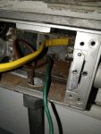
In my attached screenshot, you will see the yellow wire which is the 12/2 coming from the timer to my outlet, the bare copper wire which is the ground rod in question and the green is a grounding pigtail that was previously connected to the ground screw on the GFCI outlet. You can see that the ground rod and the pigtail are connected to a lug screwed to the metal box. The ground rod appears to just go straight down into the ground inside that conduit. I don't believe my pool is bonded as it was built in the 70s (was bonding pools a thing then?).

What is the best and correct way for me to wire this? Should I take the ground from my 12/2 connect it to the lug and then re-connect the pigtail to the outlet? Should I disconnect the ground rod completely (I have read some things about multiple grounds being an issue)?

Just want to make sure I do this as safely and correctly as possible.

IMG_20200610_201734.jpg
 

Enjoying this content?

Support TFP with a donation.

Give Support
Thread Status
Hello , This thread has been inactive for over 60 days. New postings here are unlikely to be seen or responded to by other members. For better visibility, consider Starting A New Thread.