
- Jun 22, 2014
- 47,965
- Pool Size
- 17888
- Surface
- Fiberglass
- Chlorine
- Salt Water Generator
- SWG Type
- CircuPool RJ-45 Plus
This weekend I finally installed my RJ-45. I've been stalling on this for a long time, but the 2020 COVID-19 pandemic and resulting chlorine shortage finally pushed me over the edge. Plus, it was simply time. The Circupool Installation and Operation Guide is quite good, but here are some notes and images of my own experience.
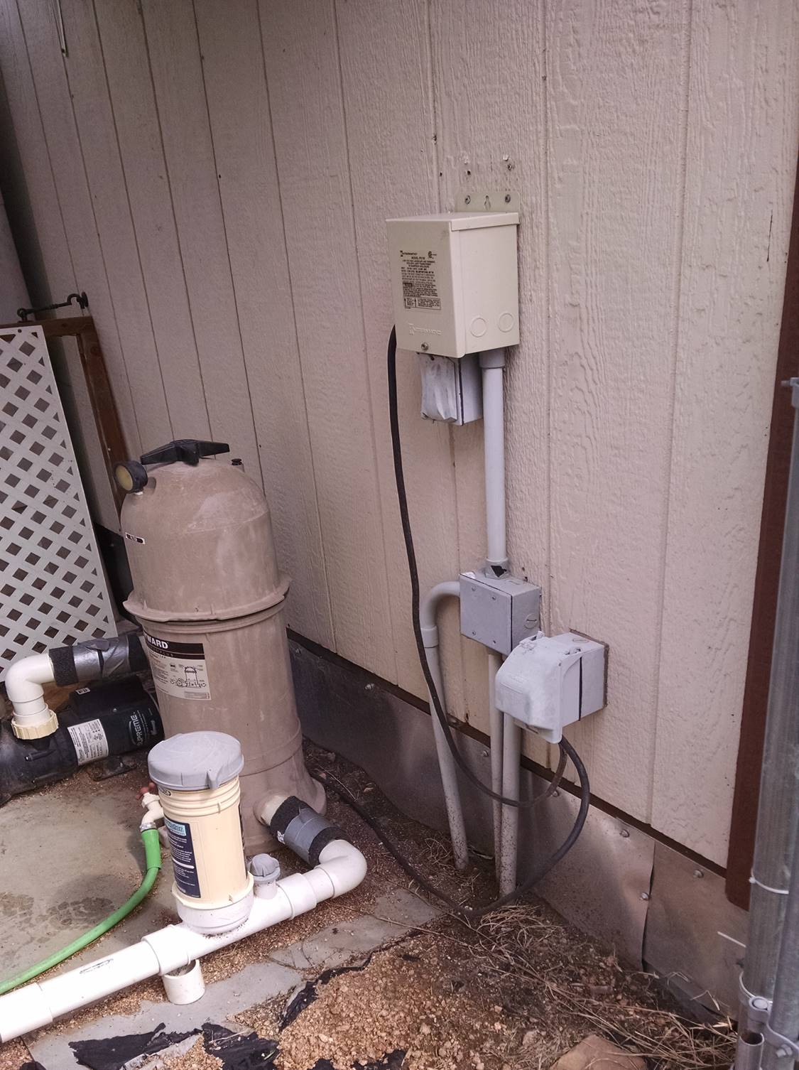
Here is mt BEFORE shot. My pad is very simple. All power is currently 120V, with an option to change to 220V later if I need to. In this pic you see an outlet at the lower right (for the SWG and pool lights) and my LED light transformer at the top.
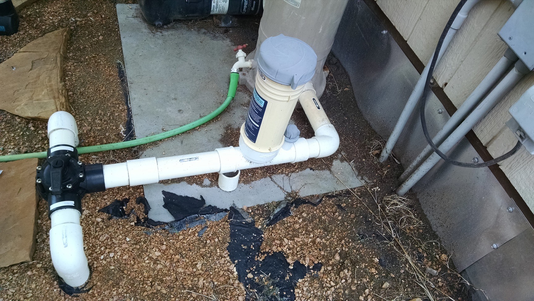
I will be replacing this inline chlorinator that I haven't used in some 6 years. My biggest challenge was positioning everything on that single straight run where the old chlorinator is since I don't have enough room elsewhere. The line out of the filter is too short for anything. The Circupool Installation and Operation Guide show various install options based on your set-up (check valves, spa, etc). The flow switch is required to have at least 6-12 inches of straight pipe before it, so in my case I put the flow switch after the cell because the cell is then considered part of that straight line measurement of 12 inches.
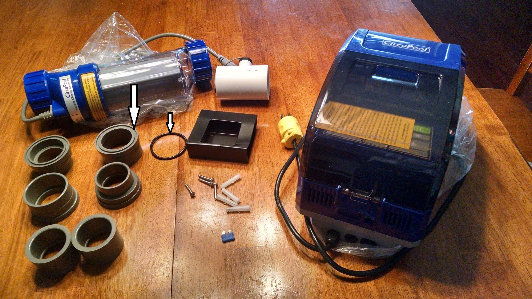
This is what you get in the package. I point-out the O-ring and union groove to let you know that the O-ring barely stays in place. In fact, it actually sticks-out of the groove a bit and kept wanting to fall-out (when installed horizontally) which made my last bit of assembly a bit challenging. The yellow plug on the control module power cord is something I installed since I had already planned to simply plug my unit to an outlet without a timer. Not shown in this picture is one black "jumper" included with the contents that is used to convert the factory-configured unit from 240V to 120V. You'll see it below. I had already installed mine.
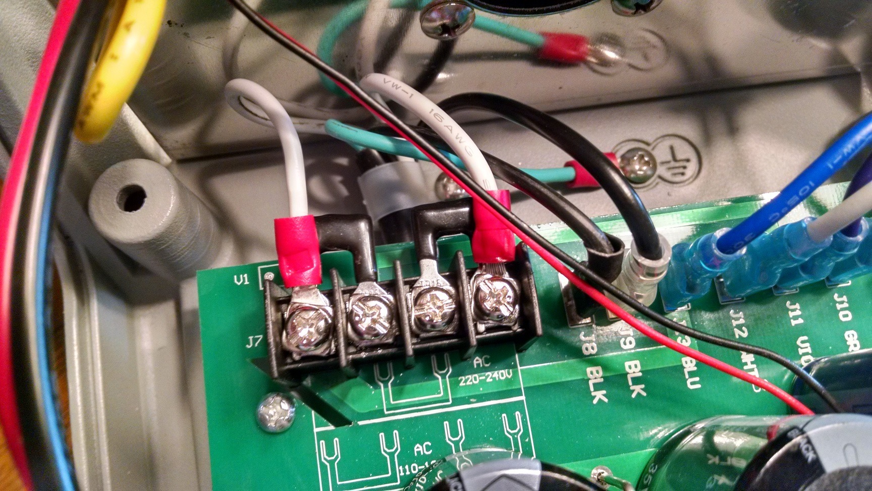
The Circupool manual is quite clear, but here's a pic of my jumpers installed and configured for 120V. It's a little tight for fingers, but take your time.
Ideally, it would be nice to have enough PVC (movement) on each end of the SWG to move/manipulate the pipes a bit. In my case I did not have that luxury - no flex at all. So with little room for error, and after removing the old chlorinator, I installed the adapter on the right with blue collar first, then installed the flow switch to the far left. This would then leave me with the final pieces to glue - the small 5-inch piece of pipe and left adapter to the cell. The arrows point to the edge of the cell itself (see next image) which is what meets-up with the face of the adapter and O-ring.
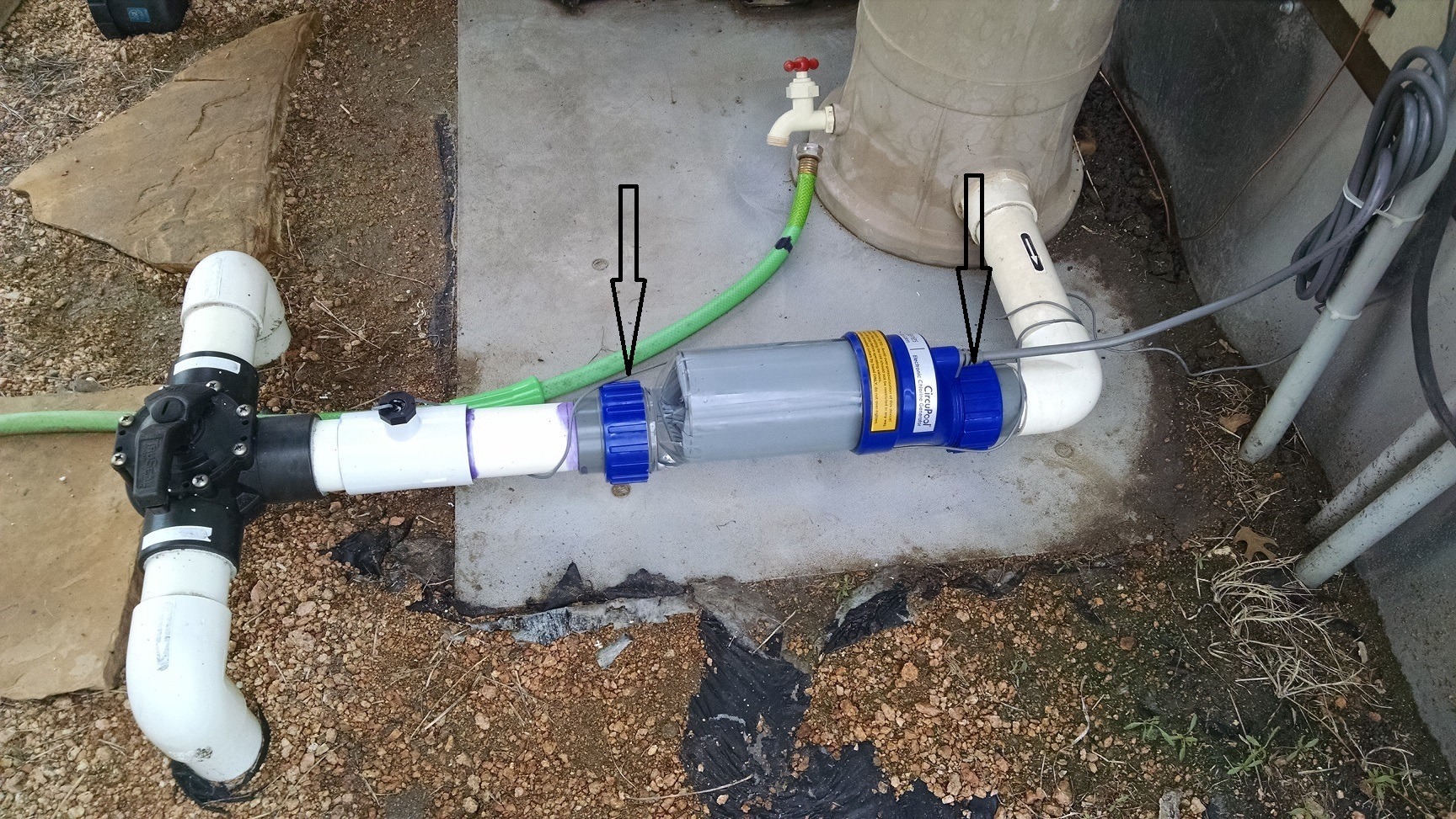
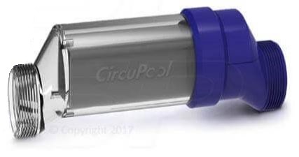
Here is the cell itself without the blue threaded collars. When you measure and cut your PVC for this to fit, these will come very close to the face of the gray adapters and O-rings.
Here is my AFTER shot with install completed. Hanging the control module on the wall was easy. It's about 22 lbs, so make sure the supporting bracket goes into some solid wood or studs. Of course your #8 copper ground needs to go the pool's bonding system. I used a "Split Bolt" from the local hardware store to connect the control module's #8 ground to the exiting pool ground near the pump. Since I converted my computer module to 120V, and already installed a plug on the end of the power cord, all I had to do was plug it in. My pump runs 24/7 (on low) because we live in the country with lots of junk in the air settling, so I need that constant surface skimming. So for now, I didn't need to use a timer. I'll just set my SWG to a very low output % setting.
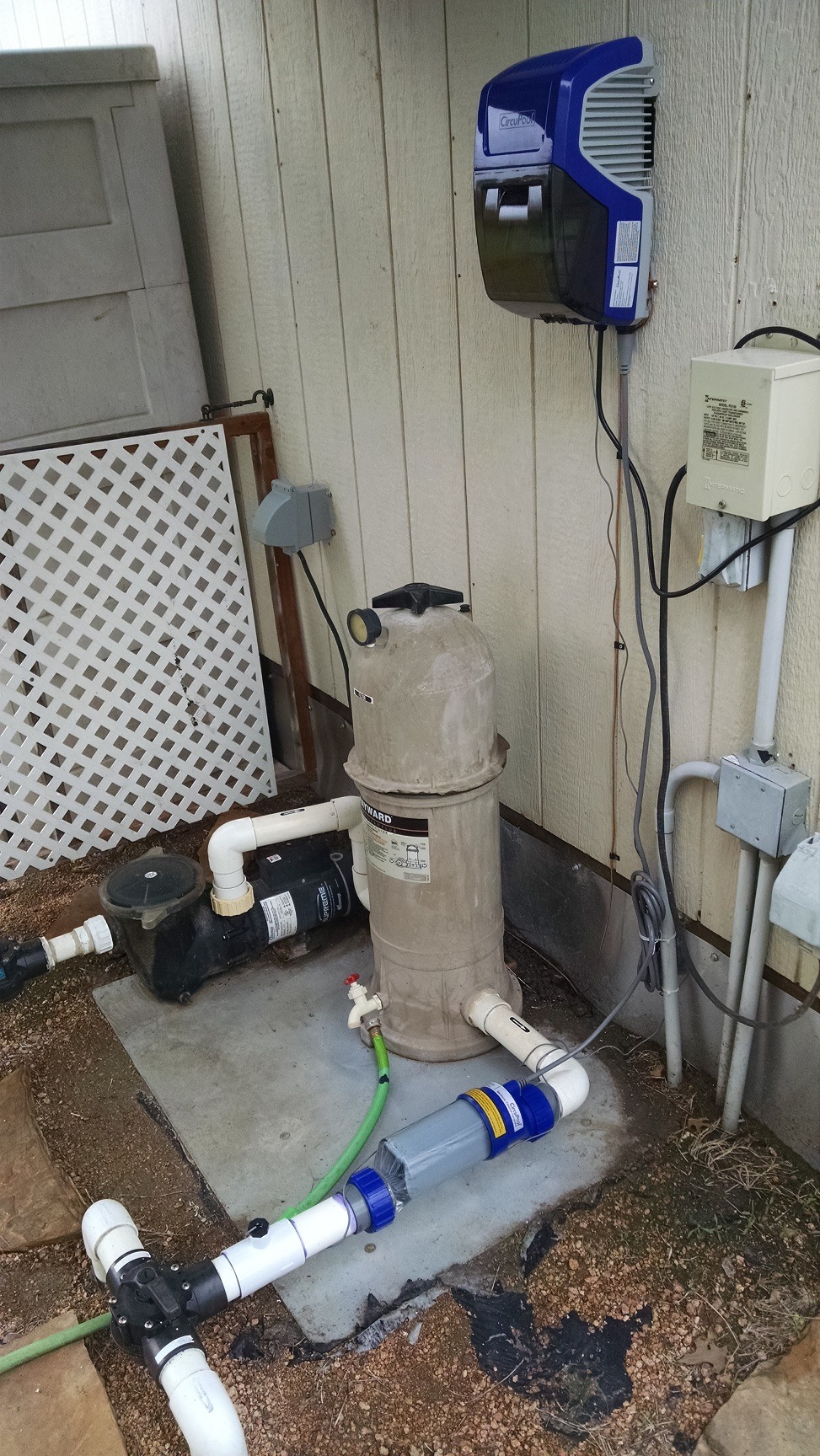
Here is the split-bolt:

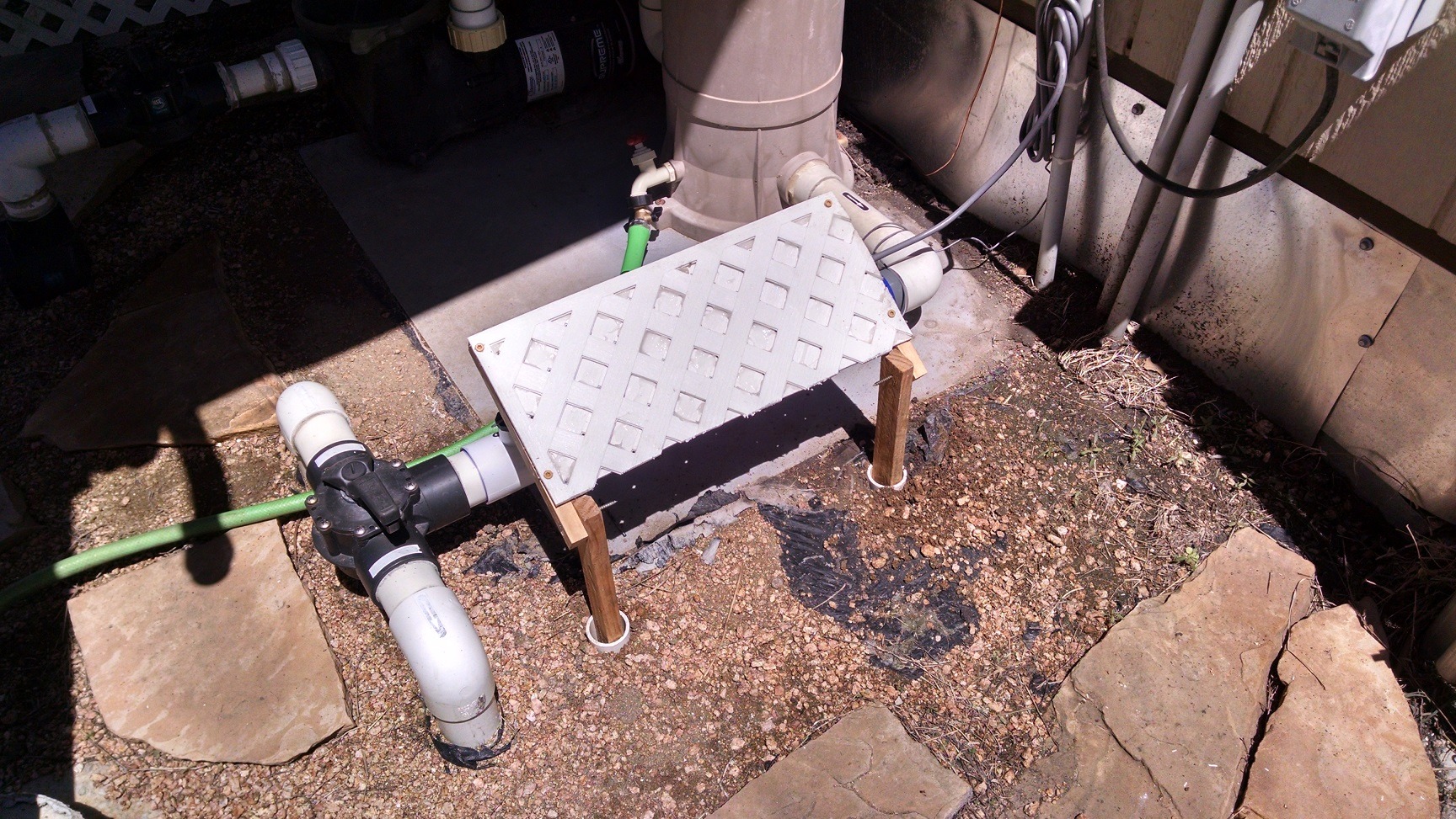
And for my final trick, I made this tiny piece to go over the SWG. My equipment pad is on the west end of the shed - full Texas sun. The lean-to and lattice help eliminate most sun & UV light, but for about 3-4 hours early each day, some light enters from the side, so I put this in to shade the SWG. Because my equipment pad area is a bit small with limited space, this also reminds us to be careful when stepping over the SWG and flow switch to pick-up our feet and not accidentally kick the unit or pull a wire by mistake.
Hope this helps anyone else about to do a similar install. If you have any questions, let me know.
Here is mt BEFORE shot. My pad is very simple. All power is currently 120V, with an option to change to 220V later if I need to. In this pic you see an outlet at the lower right (for the SWG and pool lights) and my LED light transformer at the top.
I will be replacing this inline chlorinator that I haven't used in some 6 years. My biggest challenge was positioning everything on that single straight run where the old chlorinator is since I don't have enough room elsewhere. The line out of the filter is too short for anything. The Circupool Installation and Operation Guide show various install options based on your set-up (check valves, spa, etc). The flow switch is required to have at least 6-12 inches of straight pipe before it, so in my case I put the flow switch after the cell because the cell is then considered part of that straight line measurement of 12 inches.
This is what you get in the package. I point-out the O-ring and union groove to let you know that the O-ring barely stays in place. In fact, it actually sticks-out of the groove a bit and kept wanting to fall-out (when installed horizontally) which made my last bit of assembly a bit challenging. The yellow plug on the control module power cord is something I installed since I had already planned to simply plug my unit to an outlet without a timer. Not shown in this picture is one black "jumper" included with the contents that is used to convert the factory-configured unit from 240V to 120V. You'll see it below. I had already installed mine.
The Circupool manual is quite clear, but here's a pic of my jumpers installed and configured for 120V. It's a little tight for fingers, but take your time.
Ideally, it would be nice to have enough PVC (movement) on each end of the SWG to move/manipulate the pipes a bit. In my case I did not have that luxury - no flex at all. So with little room for error, and after removing the old chlorinator, I installed the adapter on the right with blue collar first, then installed the flow switch to the far left. This would then leave me with the final pieces to glue - the small 5-inch piece of pipe and left adapter to the cell. The arrows point to the edge of the cell itself (see next image) which is what meets-up with the face of the adapter and O-ring.
Here is the cell itself without the blue threaded collars. When you measure and cut your PVC for this to fit, these will come very close to the face of the gray adapters and O-rings.
Here is my AFTER shot with install completed. Hanging the control module on the wall was easy. It's about 22 lbs, so make sure the supporting bracket goes into some solid wood or studs. Of course your #8 copper ground needs to go the pool's bonding system. I used a "Split Bolt" from the local hardware store to connect the control module's #8 ground to the exiting pool ground near the pump. Since I converted my computer module to 120V, and already installed a plug on the end of the power cord, all I had to do was plug it in. My pump runs 24/7 (on low) because we live in the country with lots of junk in the air settling, so I need that constant surface skimming. So for now, I didn't need to use a timer. I'll just set my SWG to a very low output % setting.
Here is the split-bolt:
And for my final trick, I made this tiny piece to go over the SWG. My equipment pad is on the west end of the shed - full Texas sun. The lean-to and lattice help eliminate most sun & UV light, but for about 3-4 hours early each day, some light enters from the side, so I put this in to shade the SWG. Because my equipment pad area is a bit small with limited space, this also reminds us to be careful when stepping over the SWG and flow switch to pick-up our feet and not accidentally kick the unit or pull a wire by mistake.
Hope this helps anyone else about to do a similar install. If you have any questions, let me know.


 But it's all I had at the moment. I might change them out at some point. Either with a shorter screw or perhaps with a bolt and wingnut that I can tighten by hand as needed.